Know your Ohm, and your ATEX risk
In ATEX-classified environments, a single spark can be the difference between safe operation and a catastrophic explosion. Yet many facilities overlook the most fundamental physical quantity that determines whether static electricity is safely dissipated: electrical resistance, measured in ohms. This article explains why ohm values are central to explosion protection and how to measure and document them correctly.
Static electricity in everyday life
Most people are familiar with the small shock you get when touching a door handle after walking across a synthetic carpet. It is unpleasant but entirely harmless. Your body has accumulated an electrical charge, and it discharges instantly on contact with the conductive metal.
In a production environment containing fine dust, powder or flammable vapours, the situation is fundamentally different. Even a minor electrostatic discharge can take on an entirely different character. The energy in the spark only needs to exceed what is known as the minimum ignition energy of the substance in question, and for many fine powders that value is surprisingly low.
ATEX safety is therefore not limited to explosion-proof motors, correctly sized filters and pressure-relief valves. It also requires understanding and controlling the invisible electrical charges that build up during perfectly ordinary processes such as conveying, pouring and vacuum extraction of materials.
The key point: Static electricity is always generated when two surfaces rub against each other. In ATEX zones the objective is not to prevent charge build-up, but to ensure that the charge is conducted to ground in a controlled manner before it can form a spark.
Georg Ohm and electrical resistance
In 1827 the German physicist Georg Simon Ohm published his ground-breaking work on the relationship between voltage, current and resistance. The result is what we now know as Ohm's law:
U = R × I
Voltage (U, measured in volts) = Resistance (R, measured in ohms) × Current (I, measured in amperes)
The formula can be understood intuitively through a water analogy. Think of voltage as the water pressure in a pipe, current as the volume of water flowing through, and resistance as the pipe diameter and the roughness of its walls. The greater the resistance, the harder it is for current to pass.
The unit ohm (Ω) quantifies this resistance. A material with low resistance — such as copper — conducts electricity efficiently. A material with high resistance — such as plastic or rubber — blocks current almost completely. Both properties serve practical purposes, but in an ATEX context it is low resistance that we need.
What does Ohm have to do with ATEX?
The connection between electrical resistance and explosion safety is direct and decisive. When materials are conveyed — through hoses, pipes or during transfer between containers — electrostatic charge builds up on surfaces and within the transported material. That charge must have a path to ground, and that path must have sufficiently low resistance.
Low resistance = safe dissipation
If every component in a system — hoses, pipes, fittings, vessels — has low electrical resistance and is correctly connected to ground, static charges will continuously drain away before they reach a level capable of producing a spark. The system remains in electrical equilibrium.
High resistance = dangerous charge accumulation
If even a single component has excessive resistance, the electrical path to ground is broken. Charge accumulates, voltage rises, until it reaches a level at which the air breaks down and a spark is released. In an atmosphere containing combustible dust or gas, that spark can trigger an explosion.
Standard requirements: European standards, including EN 60079-32-2 (electrostatic hazards) and EN 17348:2022 (suction hoses for ATEX), set explicit requirements for grounding and for keeping the electrical resistance of components below defined thresholds — typically below 106 Ω (1 megohm) for equipment in ATEX zones.
These requirements are not merely recommendations. They are legally binding within the EU and form the basis for both CE marking of equipment and the facility's own risk assessment under ATEX Directive 2014/34/EU.
Grounding in practice
In theory, grounding is straightforward: connect all conductive parts to earth with a conductor, and charge flows away. In practice it is far more nuanced. A green-yellow earth wire attached to a piece of equipment is only effective if the entire electrical path has sufficiently low resistance.
When does grounding fail?
- Paint and powder coating: Many metal surfaces are painted or powder-coated. The paint layer acts as an insulator and can completely sever the electrical connection, even when a ground clamp is fitted on top.
- Rust and corrosion: Oxide layers on metal surfaces increase resistance significantly. A ground connection that was adequate at installation can lose its effectiveness over time.
- Plastic components: If a plastic hose, nylon tube or rubber sleeve is part of the system without being conductive (antistatic), the earth path is broken entirely.
- Loose connections: Vibrations in production environments can loosen clamp connections over time, causing contact resistance to rise.
The critical point is that you cannot assess the quality of a ground connection by visual inspection alone. A wire can look perfectly intact and still have a resistance of several megohms due to an oxidised contact point. Only a measurement with a suitable instrument can confirm that the connection is adequate.
Equipotential bonding
Equipotential bonding is a concept often confused with grounding, yet it serves a different function. Where grounding ensures that charges can flow to earth, equipotential bonding ensures that all metal parts in a system share the same electrical potential.
Imagine two metal containers standing close together. If one has accumulated a charge and the other has not, a voltage difference exists between them. When an operator touches both containers at the same time or when the containers are brought close enough together — a discharge can occur. Equipotential bonding prevents this by connecting metal parts with a conductor so that they always remain at the same voltage level.
Important: Equipotential bonding alone does not remove charge from the system. It merely equalises voltage differences between components. Without a proper ground connection, the entire system can still carry a charge — simply at the same potential everywhere. Complete protection requires both equipotential bonding and grounding.
In practice, all conductive parts in an ATEX system should be both mutually bonded and connected to a common earth point. This ensures that neither voltage differences between components nor overall charge accumulation can develop in the system.
Common errors and myths
Over many years of working with ATEX equipment, we regularly encounter misunderstandings that can have serious consequences. Here are three of the most widespread:
The mere presence of a green-yellow wire guarantees nothing on its own. The wire may be internally broken, the clamp may sit on a painted area, or the connection may be corroded. Safety requires a documented measurement showing that the resistance from component to earth point is below the relevant threshold. Without measurement data, an earth wire is little more than decoration.
Standard plastic is an excellent insulator and accumulates electrostatic charge instead of conducting it away. In an ATEX environment, ordinary plastic hoses are therefore directly hazardous. Hoses with documented conductive or antistatic properties must be used, and their resistance should be measured regularly, because wear and ageing can alter the electrical characteristics over time. EN 17348:2022 specifies precisely which requirements suction hoses must meet.
Zone 22 is defined as an area where an explosive dust cloud occurs only rarely and for short periods during normal operation. But “rarely” does not mean “never”. Furthermore, even a thin layer of deposited dust on a hot surface can ignite through smouldering. Many serious dust explosions have occurred in areas considered low-risk. Zone 22 still demands correctly grounded and resistance-verified components.
When static electricity ignites
History contains numerous examples of electrostatic discharges causing explosions with severe consequences. As early as 1785, an explosion at an Italian bakery was documented, where fine flour dust suspended in the air was ignited. At the time the mechanism was not understood, but the incident illustrates that the problem is as old as the industrial handling of fine powders.
In modern times, plastic containers are a recurring factor in accident reports. When fine powders are poured into or out of non-conductive containers, a strong electrostatic charge builds up on the container wall. Because the plastic cannot conduct the charge away, voltage rises until a spark jumps — either to a nearby metal part or through the powder cloud itself.
International safety bodies such as the HSE (Health and Safety Executive, UK) and NFPA (National Fire Protection Association, USA) have spent decades researching the link between static electricity and dust explosions. Their conclusions are unequivocal: inadequate grounding and lack of resistance control are among the most common contributing factors in these incidents.
The lesson: Explosions caused by static electricity are not rare exceptions. They happen when basic precautions — grounding, resistance verification and correct material selection — are not in place. Every facility handling dust or powder in ATEX zones should adopt a systematic approach to managing these risks.
How to measure
Measuring electrical resistance in an ATEX system requires neither expensive equipment nor specialist training, but it does require a systematic approach and the right instrument.
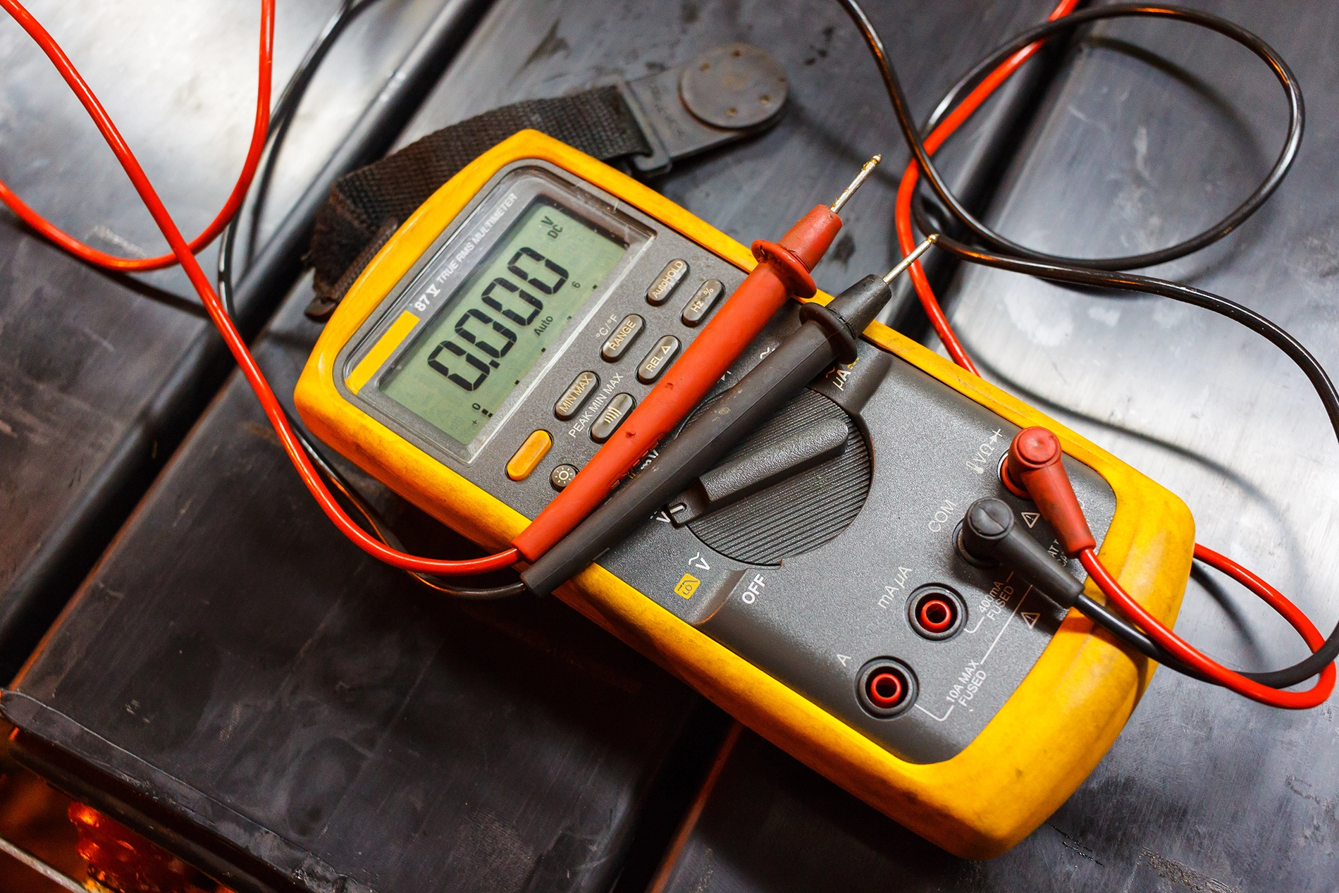
Choosing an instrument
A digital multimeter with a resistance function (ohmmeter) is sufficient for most measurements. For more precise earth-resistance readings, a dedicated ground-resistance tester may be appropriate. Select an instrument capable of measuring from low ohm values up to at least 10 MΩ (107 Ω).
Procedure
- Identify every component in the system that needs to be measured: hoses, pipes, fittings, clamp connections, vessels.
- Place one probe on the component under test and the other probe on the nearest documented earth point.
- Read the resistance and record the value together with the component location and date.
- Repeat for all critical points in the system.
Interpreting the results
The threshold depends on the specific standard and zone type, but as a general rule:
- Below 106 Ω (1 MΩ): The resistance is acceptable. Charges can be safely conducted to ground.
- Above 106 Ω: The resistance is too high. The component represents a potential ignition source and must be rectified.
Practical examples
Motor housing, measured to earth point: 0.3 kΩ (300 Ω) — Excellent. The metal connection is intact, and charges are effectively dissipated.
Suction hose, measured end-to-end: 5.4 MΩ (5,400,000 Ω) — Too high. The hose is acting as an insulator and must be replaced with a conductive or antistatic hose compliant with EN 17348:2022.
Documentation: Every measurement should be recorded with date, measurement point, reading and instrument calibration status. This documentation forms part of the facility's ATEX dossier and may be required for inspection.
Frequently asked questions
How often should resistance be measured?
There is no universal frequency, but best practice is to measure at installation, after any repair or component replacement, and thereafter at fixed intervals — typically every six or twelve months, depending on the severity of the operating environment. Hoses and flexible connections wear faster and should be measured more frequently than fixed installations.
What documentation requirements apply?
The ATEX Directive requires facilities to prepare an explosion protection document. Resistance measurements form part of the ongoing maintenance and inspection records that support this document. Measurement reports should include the date, measurement point, value, instrument used and the assessor's signature.
What should I do if a reading shows excessive resistance?
First, identify the cause: is it a corroded clamp, a painted surface, a defective hose or a loose connection? Then rectify the fault — clean contact surfaces, replace non-conductive components, re-tighten clamps, and measure again to confirm that the resistance is now below the threshold. Components with persistently high resistance must be taken out of service.
Can I use an ordinary ohmmeter?
Yes, for most routine measurements a digital multimeter with a resistance function is sufficient. The instrument should have a measurement range covering low ohms up to at least 10 MΩ, and it should be calibrated. For more specialised tasks — such as surface resistance on floors or conductive coatings — a dedicated surface-resistance meter may be necessary.
Need guidance on ATEX-compliant extraction components?
Every Ex-Vac product is engineered to meet the strictest requirements for electrical resistance and grounding. Contact us for a no-obligation review of your system, or explore our knowledge base for more technical articles.