OLI PG · air cannons

Air cannons for silos and hoppers

A pressure vessel emptied through one fast valve that lays an air blade down along the wall — at 3 to 6 bar.

Wood chips, paper, textile fibres, plastic shavings, bran. Materials with a large and irregular particle shape hold together differently from a fine powder: they interlock, span a bridge across the outlet and stay behind on the cone wall when the rest has run out. Vibration and aeration work on the mass from within and fall short. An air cannon does something else. The PG is a pressure vessel charged to 3 to 6 bar and emptied through one fast valve: between 2.6 and 21 litres of free air leave the nozzle in an instant. The jet is aimed parallel to the internal wall, and the effect is an air blade that sweeps the hopper surface clean. It does not run continuously but in shots — at an interval you set yourself, from 30 seconds to 45 minutes.

PG3–6 bar2.6–21 l per shot−20 to 80 °C6–21 kg
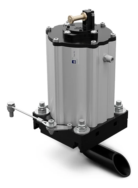
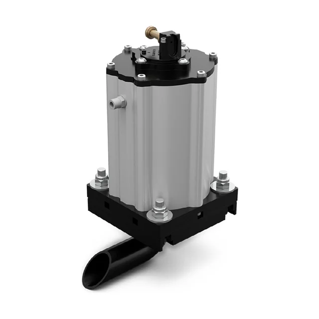
A PG air cannon seen from the front at an angle: a ribbed aluminium pressure vessel on a black mounting plate, with a coil and manual override on top and a black nozzle pipe out through the plate.
The problem

Three ways the material stays behind

An air cannon solves three things: the bridge over the outlet, the rathole through the middle and the emptying that never finishes. Any plant engineer knows the first two. The third is the one that costs most, because it does not stop production — it just eats the capacity.

Bridge over the outlet

Bridge over the outlet

Chips, flakes and fibres interlock and span an arch across the opening. The silo is full, the discharge works in empty space, and nothing comes out.

Rathole through the middle

Rathole through the middle

A narrow shaft runs down through the centre while the rest stands still along the wall. The silo looks like it is emptying, but most of the contents stay put — and get older by the day.

Incomplete clean out

Incomplete clean out

The material does come out, but a cake stays behind on the cone wall and the silo never empties completely. This is what the air blade is built for: the jet runs along the wall and takes the cake with it.

Walkthrough

Four steps through the product

Click through: from the silo that never empties to the choice between the three sizes.

01 The problem

The same silo with and without air cannonsA silo with a vertical shell and a cone below, divided by a vertical line. To the left of the line the material has formed a bridge across the cone, and beneath the bridge it is empty; along the cone wall lies a cake of material that has stayed behind, and nothing comes out of the spout. To the right, air cannons sit on the outside of the cone wall at three heights, each with a short nozzle pipe passing in through the wall. From each nozzle a narrow air blade runs down along the inner face of the wall, the cake is gone, and a stream falls out of the spout below. The line can be dragged from side to side.Without air cannonsWith the PG

Without cannons the material carries its own weight: the bridge stands across the outlet and a cake stays behind along the cone wall that never comes out. With cannons an air blade runs down along the wall and tears the cake loose. It is the same silo on both sides of the line.

02 The technology

Section through the silo wall with an air cannonA piece of sloping silo wall seen in section. The material lies above the wall and the air cannon sits below it, that is outside the silo. The cannon is an upright, ribbed pressure vessel on a square mounting plate, with a valve and coil on top and an air connection on the side. From the vessel a nozzle pipe passes up through a hole in the wall and turns in an elbow so that the mouth points down along the inner face of the wall. From the mouth a narrow, elongated air blade runs down along the wall, and the material just above the blade has been torn loose. The dimensions D for the height of the cannon and A for the side of the plate are marked on the drawing. At the top right the plate is seen from the front as a square with slotted holes in the corners and the nozzle pipe in the middle.D · 263 mmA · 160 mmThe plate from the front160 × 160 mmThe angle is set for legibility

The cannon sits on the outside of the wall, and only the nozzle goes in. The nozzle is an elbow: it turns the jet so the shot lies down like a blade along the inner face instead of drilling into the mass. The valve sits in the head and empties the vessel in an instant.

03 The installation

The compressed air circuit and the control for the air cannonsA silo with a cone, seen from the side. On the left stands a compressor, then a filter and then a flow control valve with a handwheel. Above them sits a control box, and from it thin signal lines run out to each cannon. From the valve an air line runs up alongside the silo and on into three branches, one for each height on the cone. On the outside of the cone wall the cannons sit in pairs, and from each nozzle a narrow air blade runs down along the inner face of the wall. Below, a stream of material falls out of the spout.12345

The circuit is short: a filter and a flow control valve. The difference from an aerator is that the cannon needs a signal to fire. The timer sets the interval from 30 seconds to 45 minutes, and one electronic board can take up to fifteen cannons and fire them in turn.

  1. The compressed air The PG runs on compressed air at 3 to 6 bar. The pressure decides how hard the shot is: the same cannon gives almost twice as much air at 6 bar as at 3.
  2. The filter The air has to be clean. The air quality has to be class 5.4.1. A fast valve that opens and closes many times a day is the wrong place to have dirt in the air.
  3. The control The timer is set from 30 seconds to 45 minutes, and one electronic board can control up to fifteen cannons. The coils are available from 24 volt AC and DC up to 230 volt.
  4. The cannons on the cone The vessels sit outside, and only the nozzles pass in through the wall. Each nozzle lays its blade down along the inner face. The shot is powerful: the maximum noise level is 105 dB(A), and that belongs in the choice of position.
  5. The outlet What comes out is what it is all about. The cake along the wall has been torn loose, the bridge is broken, and the cone empties all the way round instead of through a hole in the middle.

04 The choice

Which size
The PG 40 air cannonThe smallest of the three. An upright pressure vessel 223 millimetres tall above a square plate of 130 millimetres, with a nozzle pipe 27 millimetres in diameter projecting 61 millimetres from the plate.DFAØ EPG 40A 130 · B 20 · D 223 · Ø E 27 · F 61 mmAir at 3 bar2.6 lAir at 6 bar4.6 lHeight D223 mmPlate A130 × 130 mmWeight6 kg
The PG 63 air cannonThe middle size. An upright pressure vessel 263 millimetres tall above a square plate of 160 millimetres, with a nozzle pipe 42 millimetres in diameter projecting 88 millimetres from the plate.DFAØ EPG 63A 160 · B 20 · D 263 · Ø E 42 · F 88 mmAir at 3 bar6.4 lAir at 6 bar11.6 lHeight D263 mmPlate A160 × 160 mmWeight14 kg
The PG 80 air cannonThe largest of the three. An upright pressure vessel 318 millimetres tall above a square plate of 200 millimetres, with a nozzle pipe 48 millimetres in diameter projecting 104 millimetres from the plate.DFAØ EPG 80A 200 · B 25 · D 318 · Ø E 48 · F 104 mmAir at 3 bar12.5 lAir at 6 bar21 lHeight D318 mmPlate A200 × 200 mmWeight21 kg

The three are drawn to the same scale. Which one fits depends on the size of the cone, what you handle and what the compressed air can deliver — we are happy to work it through on your own silo.

The three are the same cannon in three volumes. Click between them — all three are drawn to the same scale, so the difference is there to be seen and not just read.

The technology

One shot, along the wall

An air cannon is a pressure vessel. The vessel stands full of compressed air at 3 to 6 bar and does nothing — until the valve opens. The valve is integrated in the head, it is fast, and it empties the whole vessel in an instant: 2.6 litres on the smallest at 3 bar, 21 litres on the largest at 6. Afterwards the vessel recharges, and nothing more happens until the next shot. The duty cycle is therefore discontinuous, and that is why the consumption can be so low: the cannon only uses air in the seconds it is working.

The direction is the whole point. The jet is aimed parallel to the internal wall of the silo, so that materials with an irregular shape, dry and light, flow down without any accumulation. The nozzle is an elbow: it takes the air in through the wall and turns it, so the shot lies down like a blade across the surface instead of drilling into the mass. That is the air blade, and it is what sweeps the hopper surface clean.

It is not quiet, though. The maximum noise level is 105 dB(A), and that is a figure that belongs in the planning of where the cannons sit and who works nearby. The air also has to be clean: quality class 5.4.1, with a filter and a flow control valve in the circuit.
Data

Technical specifications

ApplicationHopper and silo
Material in the siloLarge size, irregular shape, fibrous dust and flakes
Problem solvingBridge, rat-holing and incomplete clean out
Duty cycleDiscontinuous
Working pressureFrom 3 bar to 6 bar (from 43 psi to 87 psi)
Air per shot2.6 to 21 litres, depending on size and pressure
Pneumatic circuitFilter and flow control valve
Air supply qualityClass 5.4.1
Working temperature−20 to 80 °C (−4 to 176 °F)
Max noise level105 dB(A)
TechnologyHigh pressure jet
MaterialAluminium body, steel plate and aluminium head
Air inlet1/8 in BSPP on the PG 40, 1/4 in BSPP on the PG 63 and PG 80
Directives2014/34/EU category 3D and 2006/42/EC, designed to EN 1127-1 and EN 12100
PositionInternal application, in contact with the material. The vessel sits outside on the wall, the nozzle passes in through it
The dimensions

Three sizes, the same build

What separates the three is the volume of the vessel — and therefore how much air there is in one shot. A is the side of the mounting plate, B its thickness, D the overall height of the cannon, Ø E the diameter of the nozzle pipe and F how far the nozzle projects from the plate.

Air per shot in litres, dimensions in millimetres
Model3 bar6 barABDØ EFWeight
PG 402.6 l4.6 l130 mm20 mm223 mm27 mm61 mm6 kg
PG 636.4 l11.6 l160 mm20 mm263 mm42 mm88 mm14 kg
PG 8012.5 l21 l200 mm25 mm318 mm48 mm104 mm21 kg

The number in the model name follows the size of the vessel: the PG 40 is the smallest and the PG 80 the largest. The air inlet is 1/8 in BSPP on the PG 40 and 1/4 in BSPP on the other two, and the pipe diameter is 8 millimetres on all three.

Components

The vessel, the valve and what fires the shot

A PG comes with a mounting plate. The plate bolts to the silo wall, the nozzle pipe passes in through it, and the vessel stays outside. The valve is integrated in the head, and firing can be electric or fully pneumatic.

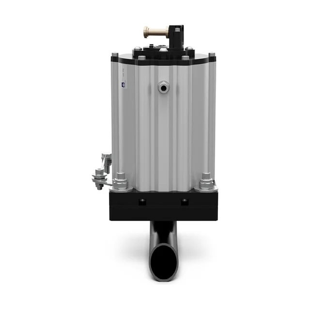
A PG air cannon seen straight from the front: the ribbed vessel on the black mounting plate, with the nozzle pipe pointing down below the plate.

The vessel and the plate PG 40 · 63 · 80

The pressure vessel itself is aluminium and stands on a square steel plate that is included. The plate has slotted holes in all four corners so it can be aligned, and the nozzle pipe passes in through the middle.

SizesPG 40, PG 63 and PG 80
Plate side130, 160 or 200 mm
Overall height223, 263 or 318 mm
Weight6, 14 or 21 kg
MaterialBody and head in aluminium, plate in steel
  1. The plate bolts on from the outside of the silo wall.
  2. The nozzle pipe passes in through the wall and turns, so the jet runs along the inner face.
  3. The vessel sits outside and can be reached for service.
  4. The mounting plate is included in the delivery.
A PG air cannon seen from behind at an angle: the coil and the manual override on top of the head, and the air connection on the side of the vessel.

The valve and the firing

The valve sits inside the head, not as a loose component in the pipe, and it is what makes the shot fast enough to become a blade rather than a puff. On top sits the coil with a manual override. Where the plant has to run without electricity at the cannon, a fully pneumatic activation kit is available instead.

ValveIntegrated in the head
Coils24 V AC and DC up to 230 V
TimerAdjustable from 30 seconds to 45 minutes
ControlElectronic board for up to 15 cannons
Without powerFully pneumatic activation kit
  1. The coil opens the valve and the vessel empties in an instant.
  2. The timer decides how often it fires.
  3. One electronic board can control up to 15 cannons and fire them in turn.
  4. The manual override sits on top of the head.

How many cannons are needed and where they should sit depends on the dimensions and angle of the cone, what you handle, and what the compressed air can deliver. Tell us, and we come back with a size, a number and a layout.

Application

Where it sits and what it works in

PlantSilos and hoppers
MaterialsPowders of large particle size and irregular shape, fibrous powders and flakes. Typically wood fibres, textile fibres, paper, plastics and bran
BenefitsCompact design with integrated solenoid valve, suitable for bridge breaking, economical, easy to install, low air consumption and mounting plate included
SectorsBuilding and construction, food and feed, heavy industries, plants and machinery, plastics and chemical processing, recycling and environment technology, and renewable energies
Ex areasConforms to directive 2014/34/EU in category 3D, that is dust zone 22

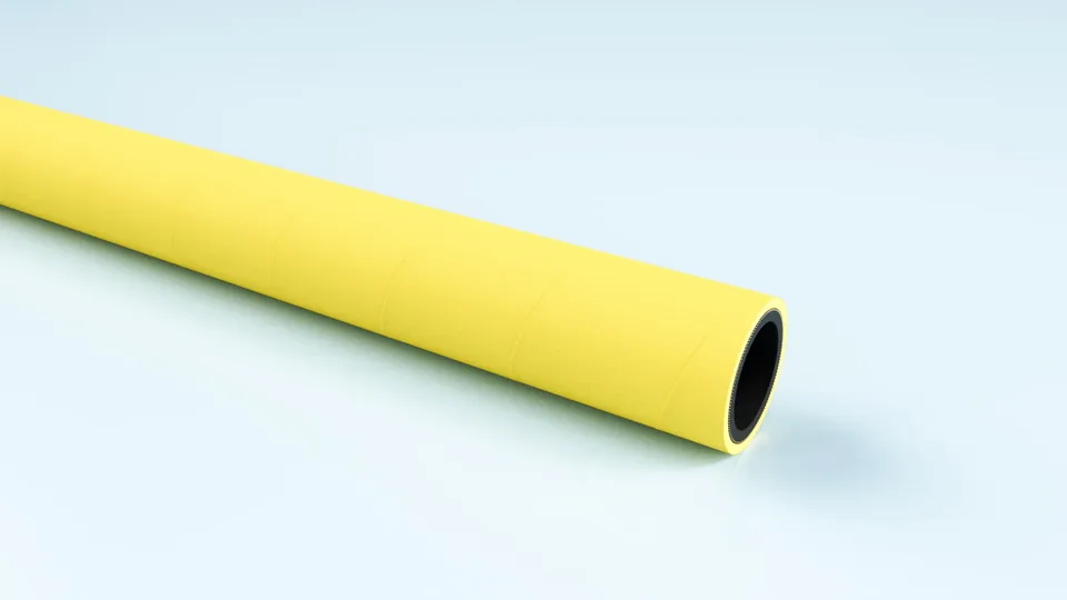
Yellow EPDM compressed air hose, coiled.

FlexCore

ARIACORD/YELLOW

Rugged EPDM hose for compressed air and water, 25 bar. Weather and UV resistant, so it can live outdoors beside the silo.

Material
EPDM
Inner diameter
32–76 mm
Working pressure
25 bar
Temperature
-30 to +80 °C

See the full product page on FlexCore →

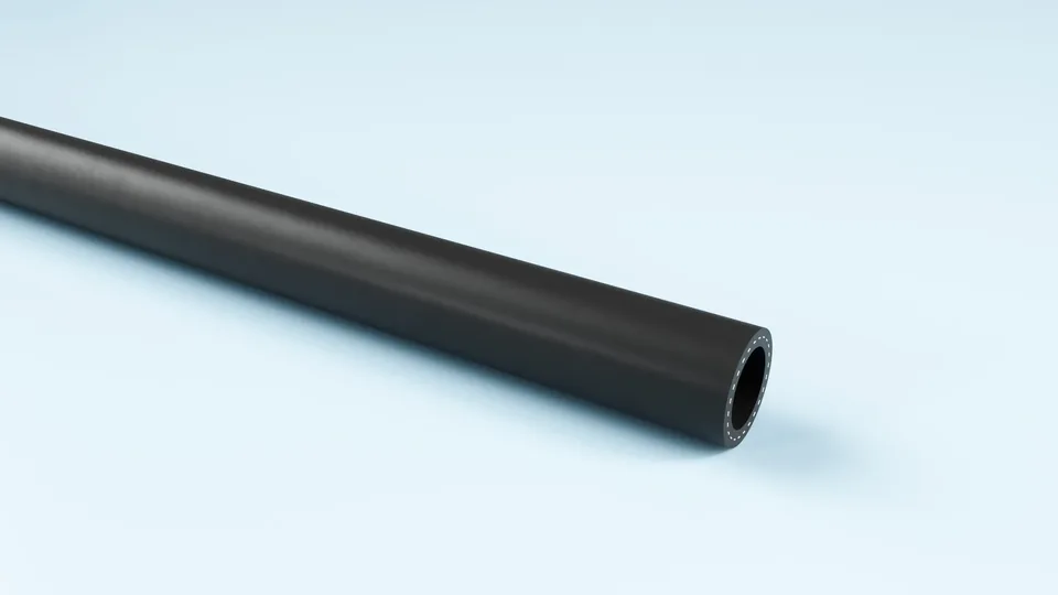
Black TPE air hose, coiled.

FlexCore

ARIAFORM/15

TPE air hose for industry and workshop. Handles water, air and oil-laden compressed air, and is light enough to move around.

Material
TPE
Inner diameter
16–25 mm
Working pressure
15 bar
Temperature
-30 to +80 °C

See the full product page on FlexCore →

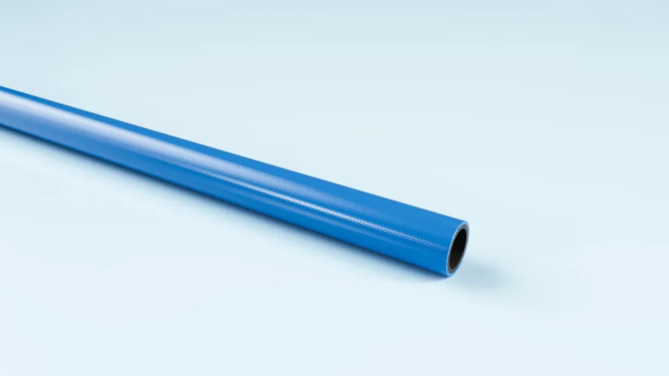
Blue polyurethane hose, coiled.

FlexCore

ARIAFORM/TPU

Light polyurethane hose for tools and reel systems. The softest of the three, where the hose has to follow the work.

Material
TPU
Inner diameter
6–13 mm
Working pressure
20 bar
Temperature
-30 to +80 °C

See the full product page on FlexCore →

Portrait of a technical adviser at Particulair.

Technical advice

Which size, and how many?

Tell us the dimensions and angle of the cone, what you handle, and what the compressed air can deliver. We come back with a size, a number and a price — not with a catalogue.

Contact us Try the product selector