OLI I100 · fluidisation pads

Fluidisation pads for silos and hoppers

A flat pad in the cone wall that lays air in under the material across its whole face — at 0.2 bar.

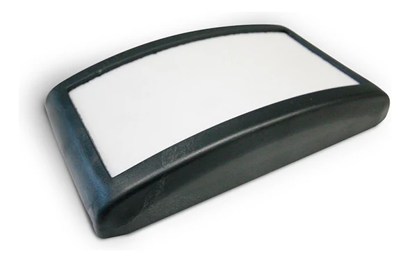
A dry, fine powder that has stood still holds on to itself. It forms a bridge over the outlet, a rathole through the middle, or it settles like a cake along the cone wall. The I100 is OLI's fluidisation pad for exactly that: a flat pad of 166 by 98 millimetres that sits on the inside of the wall and blows air out through a porous face. Because the face is gently domed, the air leaves at a wide angle rather than as a jet — the material just above the pad becomes a layer that can flow. It happens at 0.2 bar, the lowest working pressure in the whole range. It is also called an aeration pad and a fluidizing plate.

I1000.2 bar30 Nl/min−20 to 80 °C166 × 98 mm
An I100 fluidisation pad with a white porous face in a black polyamide body, seen from the front at an angle.
The problem

Three ways a dry powder holds on to itself

The catalogue puts it in one sentence: low pressure aeration prevents bridges, rat holes, lumps and deposits on the bottom of the cone. Behind those four words lie three situations any plant engineer knows.

Bridge over the outlet

Bridge over the outlet

The powder spans an arch across the opening and carries its own weight. The silo is full, but nothing comes out, and the discharge works in empty space.

Rathole through the middle

Rathole through the middle

A narrow shaft runs down through the centre while the rest stands still along the wall. The silo appears to empty, but most of the contents stay where they are.

Lumps and deposits in the cone

Lumps and deposits in the cone

The material does come out, but slowly, and a cake stays behind on the cone wall. This is what a pad is built for: the air is laid in exactly where the cake sits.

Walkthrough

Four steps through the product

Click through: from the silo that will not empty to the choice between the three aerators that can sit in the same silo.

01 The problem

The same silo with and without fluidisation padsA silo with a vertical shell and a cone below, divided by a vertical line. To the left of the line the powder has formed a bridge across the cone, and beneath the bridge it is empty; along the cone wall lies a cake of material that has stayed behind. To the right, flat fluidisation pads sit on the cone wall at three heights. From each pad arrows spread out in a wide fan along the wall, the material is loose, and a stream falls out of the spout below. The line can be dragged from side to side.Without aerationWith the I100

Without air the powder carries its own weight: the bridge stands across the outlet and a cake stays behind along the cone wall. With air the layer nearest the wall loses its cohesion and begins to slide. It is the same silo on both sides of the line.

02 The technology

Section through the cone wall with a fluidisation padA piece of sloping silo wall seen in section. The material lies above the wall. Inside the material the pad sits as a low, gently domed shell 166 millimetres long and 32 high; beneath the shell lies a cavity in which the air distributes itself. In the middle of the underside a connection passes out through a hole in the wall, and outside sit a washer and an air line. From the pad five arrows spread out in a wide fan up into the material. The dimensions B of 166 millimetres and C of 32 are marked on the drawing. At the top right the pad is seen from above as a rectangle of 166 by 98 millimetres with a lighter porous face in the middle and the connection as a small circle at the centre.B · 166 mmC · 32 mmThe pad from above166 × 98 mmThe angle is set for legibility

The porous face turns towards the material and the connection passes out through the wall. Beneath the face lies a cavity in which the air distributes itself before passing through. Because the face is gently domed — 32 mm over a length of 166 — the air leaves at a wide angle and runs along the wall to both sides.

03 The installation

The compressed air circuit for the fluidisation padsA silo with a cone, seen from the side. On the left stands a compressor, then a filter and then a flow control valve with a handwheel. From the valve an air line runs up alongside the silo and on into three branches, one for each height on the cone. On the cone wall the pads sit in pairs, and from each pad the air spreads in a wide fan. Below, a stream of material falls out of the spout. There is neither a control box nor a solenoid valve in the circuit.12345

The circuit is short. The catalogue names two things: a filter and a flow control valve. There is neither a control box nor a solenoid valve, because the I100 runs continuously and is not cycled. The pressure is 0.2 bar and each pad uses 30 normal litres a minute.

  1. The compressed air The I100 runs on ordinary compressed air at 0.2 bar. That is the lowest working pressure in the whole Flow Aids range, and the pressure is rarely the limiting factor.
  2. The filter The air has to be dry. The catalogue specifies quality class 5.4.1, and a porous face is precisely where damp powder takes hold.
  3. The flow control valve The second of the two components the catalogue names. Each pad uses 30 normal litres a minute at 0.2 bar, and it is that figure times the number of pads the supply has to carry.
  4. The pads in the cone The pads sit on the inside with the porous face towards the material. Each one lays air in across a face of 140 by 70 millimetres, not through a point.
  5. The outlet What comes out is what it is all about. The layer nearest the wall has become something that can flow, and the cone can then empty all the way round instead of through a hole in the middle.

04 The choice

Which aerator
The I100 fluidisation pad in a silo wallA low, wide shell of 166 by 32 millimetres lies on the inside of the wall. Five arrows spread out in a wide fan from its whole upper face.I100 fluidisation pad166 × 98 × 32 mmWorking pressure0.2 barAir consumption30 Nl/minTemperature−20 to 80 °CMountingInternal
The U aeration nozzle in a silo wallA round nozzle 66 millimetres in diameter and 48 long sits in the wall with its body passing through. Three arrows rise from the face of the nozzle in a narrower fan than the pad's.U aeration nozzleØ66 · 48 mmWorking pressure0.2–1 barAir consumption27–96 Nl/minTemperature−20 to 80 °CMountingFrom outside
The VBS bin aerator in a silo wallA bell-shaped disc 104 millimetres in diameter sits on the inside of the wall with the stem passing through. Three arrows rise almost in parallel, gathered into one direction.VBS bin aeratorØ104 mmWorking pressure0.8–6 barAir consumption130–1150 Nl/minTemperature−40 to 235 °CMountingInternal

The three are drawn to the same scale. Which one fits depends on the material, the temperature and what the compressed air can deliver — we are happy to work it through on your own silo.

The catalogue itself lines the three up in the same silo. They solve the same thing, but not in the same way: the pad lays air in across a face, the nozzle through a point, and the vibro-aerator concentrates the air towards the outlet at a much higher pressure. Click between them — all three are drawn to the same scale.

The technology

A wide angle instead of a jet

A nozzle blows the air out through one hole. A pad blows it out through a face. The top of the I100 is a porous membrane in high density polyethylene measuring 140 by 70 millimetres, and beneath it lies a cavity in which the air first distributes itself. So it does not come out in one place, but across the whole face at once.

The shape does the rest. The face is not flat but gently domed — 32 millimetres high over a length of 166 — and the semi-convex shape guarantees a wide emission angle. The air therefore runs out along the wall to both sides instead of drilling up into the material. The layer nearest the wall loses its internal cohesion and behaves like a liquid. That is what is meant by creating a fluid bed.

It does not take much. The working pressure is 0.2 bar and the consumption 30 normal litres a minute per pad — the lowest in the entire Flow Aids range. In return the air has to be dry: quality class 5.4.1 is required, and a porous face is precisely where damp powder would take hold.
Data

Technical specifications

ApplicationHopper and silo
Material in the siloFine, light and dry powders (cement and lime)
Problem solvingBridge and rat-holing
Duty cycleContinuous
Working pressure0.2 bar (2.9 psi)
Air consumption30 Nl/min (1.05 cfm) per pad at 0.2 bar
Pneumatic circuitFilter and flow control valve
Air supply qualityClass 5.4.1
Working temperature−20 to 80 °C (−4 to 176 °F)
TechnologyFluidisation
MaterialHigh density polyethylene, polyamide body
Connection1/4 in BSPP
Dimensions166 × 98 × 32 mm
PositionInternal, in contact with the material
The dimensions

One version, four dimensions

The I100 comes in one size. A is the short side, B the long side, C the height above the mounting face, and D the thread of the connection on the back.

Dimensions in millimetres
ModelAir consumption at 0.2 barABCD
I10030 Nl/min (1.05 cfm)98 mm166 mm32 mm1/4″ BSPP

The membrane window in the porous face measures 140 by 70 millimetres. That is the area the air actually leaves through, and therefore the one that has to face the material.

Components

The pad and the two ways of getting it into the wall

An I100 sits on the inside of the cone with the porous face towards the material. The connection passes out through the wall and the air line goes on from the outside. Where the cone cannot be reached from the inside, the pad comes on a stainless plate mounted externally.

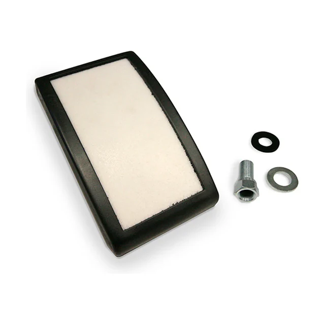
An I100 pad with a hexagonal threaded nut, a rubber gasket and a washer beside it.

The pad I100

The porous face in high density polyethylene sits in a polyamide body. The connection is on the back, and with it come the rubber gasket, the washer and the nut — what holds the pad against the wall from the inside.

Dimensions166 × 98 × 32 mm
Porous face140 × 70 mm
Connection1/4 in BSPP
MaterialHigh density polyethylene, polyamide body
Working pressure0.2 bar
  1. The porous face turns towards the material.
  2. The connection sits in the middle of the back and passes out through the wall.
  3. The gasket seals between pad and wall.
  4. The air line goes on from the outside, onto the 1/4 in BSPP thread.
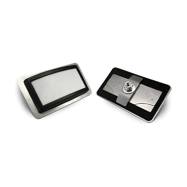
An I100 pad mounted on a stainless plate with a black gasket frame, seen from the front and the back.

External mounting

On a silo where the cone cannot be reached from the inside, the pad sits on a stainless plate with a gasket frame. The plate bolts on from the outside, and the pad still ends up with the porous face towards the material.

PlateStainless steel
SealingGasket frame around the pad
MountingFrom the outside
  1. Used where there is no access into the silo.
  2. The plate spreads the load over a larger area of the wall.
  3. The pad itself is the same as above.

Which of the two fits depends on what the wall is made of, how thick it is, and whether there is access into the silo. Tell us, and we come back with the right version and a number of units.

Application

Where it sits and what it works in

PlantSilos and hoppers
MaterialsFine, light and dry powders. The catalogue names cement and lime
TasksSilo and hopper emptying, filter cleaning and big-bag emptying
SectorsBuilding and construction, food and feed, heavy industries, plants and machinery, plastics and chemical processing, recycling and environment technology, and renewable energies
Food powdersFor powders in food production we recommend the VB vibro-aerators rather than the pads

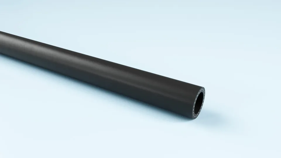
Black TPE air hose, coiled.

FlexCore

ARIAFORM/15

TPE air hose for industry and workshop. Handles water, air and oil-laden compressed air, and is light enough to move around.

Material
TPE
Inner diameter
16–25 mm
Working pressure
15 bar
Temperature
-30 to +80 °C

See the full product page on FlexCore →

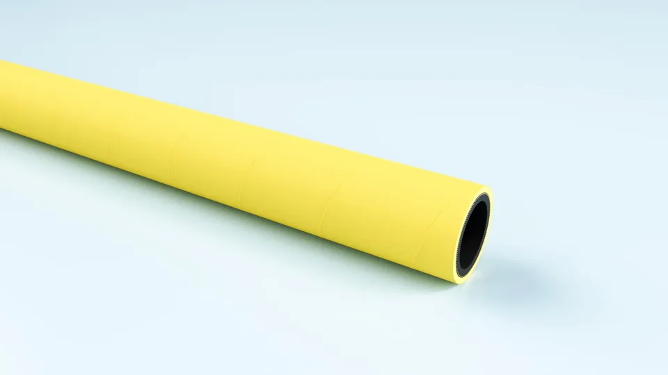
Yellow EPDM compressed air hose, coiled.

FlexCore

ARIACORD/YELLOW

Rugged EPDM hose for compressed air and water, 25 bar. Weather and UV resistant, so it can live outdoors beside the silo.

Material
EPDM
Inner diameter
32–76 mm
Working pressure
25 bar
Temperature
-30 to +80 °C

See the full product page on FlexCore →

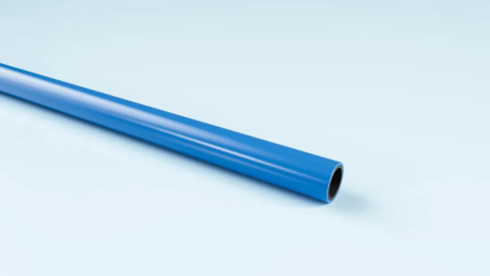
Blue polyurethane hose, coiled.

FlexCore

ARIAFORM/TPU

Light polyurethane hose for tools and reel systems. The softest of the three, where the hose has to follow the work.

Material
TPU
Inner diameter
6–13 mm
Working pressure
20 bar
Temperature
-30 to +80 °C

See the full product page on FlexCore →

Portrait of a technical adviser at Particulair.

Technical advice

How many pads does your cone need?

Tell us the dimensions and angle of the cone, what you handle, and what the compressed air can deliver. We come back with a number, a layout and a price — not with a catalogue.

Contact us Try the product selector