OLI PS · pneumatic hammers

Pneumatic hammers for silos and hoppers

One blow against a welded plate — 8,4 to 153 joules at 3 to 6 bar, without a single hole in the wall.

Flour, detergents, phosphates, fertilizer, lime, cement, clay, pigments. Hygroscopic material clings to the wall and compacts under its own weight, and then making it lighter does not help — it stays where it sits. Air and vibration work on the mass. A hammer works on the wall. The PS charges with compressed air at 3 to 6 bar and delivers one blow: a piston inside the housing strikes a plate welded to the outside of the wall, and the blow travels through the steel and shakes the layer loose. Between 8.4 and 153 joules, depending on size and pressure. Nothing enters the silo, and not one hole has to be drilled — the plate is welded on, and that is the whole installation. Which is why it can also go on a plant that is already running.

PS3–6 bar8.4–153 J−20 to 80 °C5.1–25.6 kg
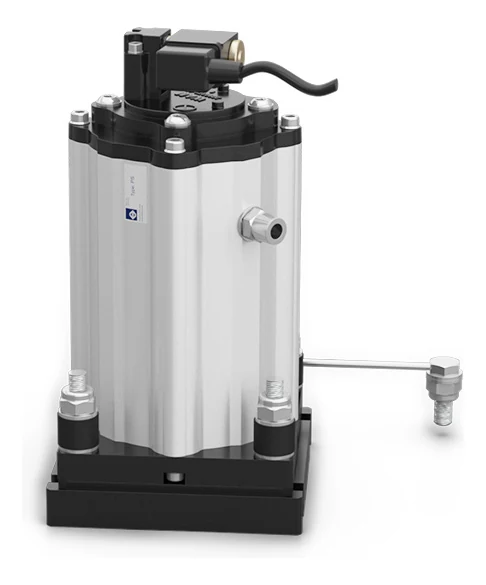
A PS pneumatic hammer of the flat plate type, seen from the front at an angle: a ribbed aluminium housing with a solenoid valve and a black cable on top, an air connection on the side, and the housing bolted down on four studs with black rubber washers over a black square plate.
The problem

Three ways the material stays behind

A pneumatic hammer solves three things: the bridge over the outlet, the rathole through the middle and the emptying that never finishes. What they have in common is that the material carries its own weight or clings to the steel, and that a layer which has once set does not let go by itself.

Bridge over the outlet

Bridge over the outlet

The material compacts under its own weight and spans an arch across the opening. The silo is full, the discharge works in empty space, and nothing comes out.

Rathole through the middle

Rathole through the middle

A narrow shaft runs down through the centre while the rest stands still along the wall. The silo looks like it is emptying, but most of the contents stay put — and get older by the day.

Incomplete clean out

Incomplete clean out

The material does come out, but a layer stays behind on the cone wall and the silo never empties completely. Hygroscopic material clings to the steel, and the layer grows with every batch.

Walkthrough

Four steps through the product

Click through: from the hopper that never empties to the choice between the two versions.

01 The problem

The same hopper with and without pneumatic hammersA silo with a vertical shell and a cone below, divided by a vertical line. To the left of the line the material has formed a bridge across the cone, and beneath the bridge it is empty; along the cone wall lies a layer of material that has stayed behind, and nothing comes out of the spout. To the right, pneumatic hammers sit on the outside of the cone wall at three heights. None of them passes through the wall: each hammer stands on a plate on the outside of the steel. From each point of impact a star and three arcs spread into the material, the layer is gone, and a stream falls out of the spout below. The line can be dragged from side to side.Without hammersWith the PS

Without hammers the material carries its own weight: the bridge stands across the outlet and a layer stays behind along the cone wall that never comes out. With hammers the blow travels through the steel and shakes the layer loose from the wall inwards. It is the same hopper on both sides of the line.

02 The technology

Section through the silo wall with a pneumatic hammerA piece of sloping silo wall seen in section. The material lies above the wall and the hammer sits below it, that is outside the silo. The wall is unbroken — there is no hole. On the outer face a square steel plate is welded on with a weld bead at each end, and on the plate stands the hammer: four bolts, and above them an upright, ribbed aluminium housing with a valve block and coil on top and an air connection on the side. Inside the housing the piston shows as a dark block with an arrow pointing down towards the plate. On the other side of the wall, inside the material, a star and three arcs spread away from the point of impact. The dimensions D for the length of the housing, B for the thickness of the plate and A for the side of the plate are marked on the drawing. At the bottom left the plate is seen from the front as a square with four bolt holes and a round flange in the middle.D · 263 mmB · 20 mmA · 160 mmThe plate from the front160 × 160 mmThe angle is set for legibility

The hammer sits on the outside of the wall, and nothing passes in. The plate is welded on — the wall is intact, no hole has been drilled — and the piston inside the housing strikes the plate. The blow travels through the steel and tears the layer loose on the other side.

03 The installation

The compressed air circuit and the control for the hammersA silo with a cone, seen from the side. On the left stands a compressor, then a filter and then a flow control valve with a handwheel. Above them sits a control box, and from it thin signal lines run out to each hammer. From the valve an air line runs up alongside the silo and on into two drop lines, one down each side of the cone. On the outside of the cone wall the hammers sit in pairs at three heights, and from each point of impact a star and three arcs spread into the material. Below, a stream of material falls out of the spout.12345

The circuit is short: a filter and a flow control valve. The hammer needs a signal to strike, and the timer sets the interval from 30 seconds to 45 minutes. One electronic board can take up to fifteen hammers and fire them in turn.

  1. The compressed air The PS runs on compressed air at 3 to 6 bar. The pressure decides the blow: the same hammer gives more than twice the energy at 6 bar as at 3.
  2. The filter The air has to be clean. The air quality has to be class 5.4.1. The circuit is short — a filter and a flow control valve — and there is nothing else between the compressor and the hammer.
  3. The control The timer is set from 30 seconds to 45 minutes, and one electronic board can control up to fifteen hammers. The coils are available from 24 volt AC and DC up to 230 volt. Where the plant has to run without electricity at the hammer, a fully pneumatic kit is available.
  4. The hammers on the cone Everything sits outside, and nothing passes through the wall. Each blow strikes its own welded plate. The blow is powerful: the maximum noise level is 125 dB(A), and that belongs in the choice of position.
  5. The outlet What comes out is what it is all about. The layer along the wall has been shaken loose, the bridge is broken, and the cone empties all the way round instead of through a hole in the middle.

04 The choice

Which version
The pneumatic hammer in type AA vertical silo wall seen in section, with the material to the right and open air to the left. On the outer face sits a flared foot, wide against the wall and narrow towards the hammer, welded on at top and bottom. On the foot stands the hammer: four bolts and above them a horizontal, ribbed aluminium housing with a valve block at the far end. Inside the housing the piston shows with an arrow towards the wall, and on the inner face a star and three arcs spread into the material. The dimensions A1 for the width of the foot, B1 for its depth and D for the length of the housing are marked on the drawing.DB1A1Type AFor steel 3 mm and thinnerA1 · foot width160 · 200 · 250 mmB1 · foot depth80 · 95 · 119 mmWeight6.7 · 15.9 · 25.6 kgFigures are forPS 40 · PS 63 · PS 80
The pneumatic hammer in type BA vertical silo wall seen in section, with the material to the right and open air to the left. On the outer face sits a flat steel plate, welded on at top and bottom. On the plate stands the hammer: four bolts and above them a horizontal, ribbed aluminium housing with a valve block at the far end. Inside the housing the piston shows with an arrow towards the wall, and on the inner face a star and three arcs spread into the material. The dimensions A for the side of the plate, B for its thickness and D for the length of the housing are marked on the drawing.DBAType BFor steel thicker than 3 mmA · plate side130 · 160 · 200 mmB · plate thickness20 · 20 · 25 mmWeight5.1 · 13.1 · 20.1 kgFigures are forPS 40 · PS 63 · PS 80

The two are drawn to the same scale. The thickness of the steel decides: 3 millimetres or less is type A, over 3 millimetres is type B. If you are unsure what the hopper is made of, we are happy to work it through with you.

Not which size — that is in the table above. The choice you actually face is which plate the hammer is going to strike, and it is decided by one figure you can measure on your own plant: how thick the steel is. Click between the two — both are drawn to the same scale.

The technology

One blow, through the steel

Inside the housing sits a piston. Compressed air at 3 to 6 bar drives it forward, and it strikes a steel plate welded to the outside of the silo wall. That is the whole mechanism: one blow, and then nothing until the next one. The energy runs from 8.4 joules on the smallest at 3 bar to 153 joules on the largest at 6 — and the force from 199 to 2186 newtons. The duty cycle is discontinuous, and that is why the consumption can be so low: the hammer only uses air in the instant it strikes. The timer decides how often, and can be set from 30 seconds to 45 minutes.

What separates a hammer from everything else in the range is where the work is applied. An aerator and an air cannon send air into the material and work on the mass. The hammer sends nothing in. The compressed air stays inside the housing, and what reaches the material is the blow through the steel. That is why it works on what clings to the wall rather than what sits loose in the mass — and why the installation needs no drilling at all. The plate is welded to the wall from the outside, the hammer bolts onto the plate, and that is it. The wall is intact afterwards, which is also why the range can go on a plant that is already running.

It is not quiet, though. The maximum noise level is 125 dB(A), the highest figure in the whole range. It belongs in the planning of where the hammers sit and who works nearby. If noise is what decides the matter, the K and F series sit at 80 dB(A), and if the material is fine and dry, a bin aerator does the job with no impact at all. The air also has to be clean: quality class 5.4.1, with a filter and a flow control valve in the circuit.
Data

Technical specifications

ApplicationHopper and silo
Material in the siloAll kinds of powders and granular material, hygroscopic included
Problem solvingBridge, rat-holing and incomplete clean out
Duty cycleDiscontinuous
Working pressureFrom 3 bar to 6 bar (from 43 psi to 87 psi)
Impact energy8.4 to 153 joules, depending on size and pressure
Impact force199 to 2186 newtons, depending on size and pressure
Air per blow2.6 to 21 litres, depending on size and pressure
Pneumatic circuitFilter and flow control valve
Air supply qualityClass 5.4.1
Working temperature−20 to 80 °C (−4 to 176 °F)
Max noise level125 dB(A)
TechnologySingle impact
MaterialAluminium body, steel attachment plate and aluminium head
Air inlet1/8 in BSPP on the PS 40, 1/4 in BSPP on the PS 63 and PS 80. Pipe diameter 8 mm on all three
Ex areasII3D Ex h IIIC T85 °C Dc, with the ATEX kit
PositionExternal application, not in contact with the material. The plate is welded to the outside of the wall and the hammer bolts onto the plate
The dimensions

Three sizes, the same build

What separates the three is the size of the blow. D is the length of the housing — the dimensions of the plate depend on whether it becomes type A or type B, and they are further down. Energy and force are one blow, not a value per minute, and the air is what one blow costs.

Energy in joules and force in newtons per blow, air in litres per blow, dimensions in millimetres
ModelEnergy 3 barEnergy 6 barForce 3 barForce 6 barAir 3 barAir 6 barDØ pipeAir inlet
PS 408.4 J18.1 J199 N429 N2.6 l4.6 l223 mm8 mm1/8″ BSPP
PS 6328.8 J62.0 J589 N1268 N6.4 l11.6 l263 mm8 mm1/4″ BSPP
PS 8059.2 J153.0 J846 N2186 N12.5 l21 l318 mm8 mm1/4″ BSPP

The number in the model name follows the size of the hammer: the PS 40 is the smallest and the PS 80 the largest. The air inlet is 1/8 in BSPP on the PS 40 and 1/4 in BSPP on the other two, and the pipe diameter is 8 millimetres on all three. The letter D is the length of the housing; A and B belong to the flat plate and A1 and B1 to the flared foot.

Components

The plate, the weld and the ATEX kit

The hammer comes with the plate it is going to strike. The plate is welded to the outside of the silo — nothing is drilled — and the hammer bolts onto it. Which plate it becomes is decided by one thing: how thick the steel is in the vessel the hammer is going on.

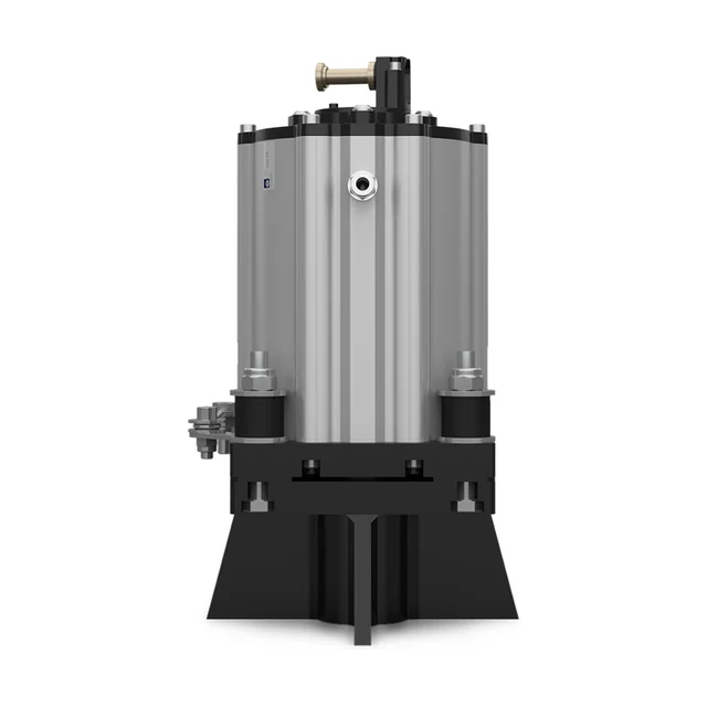
A PS pneumatic hammer of the flared foot type, seen straight from the front: a ribbed aluminium housing on four studs with black rubber washers, mounted on a black plate, and below the plate a black foot that widens outwards towards the bottom.

The plate and the weld PS 40 · 63 · 80

There are two versions, and the thickness of the steel decides which. If the wall of the vessel is 3 millimetres or thinner, it is type A with the flared foot. If the steel is thicker, it is type B with the flat plate. The plate is welded on from the outside, and that is the whole operation — the wall is intact afterwards.

Type A, wall ≤ 3 mmA1 160, 200 or 250 mm · B1 80, 95 or 119 mm
Type A, weight6.7, 15.9 or 25.6 kg
Type B, wall > 3 mmA 130, 160 or 200 mm · B 20, 20 or 25 mm
Type B, weight5.1, 13.1 or 20.1 kg
Stainless versionType B in AISI 304
MaterialHousing and head in aluminium, plate in steel
  1. The plate is welded to the outside of the silo. No hole is drilled.
  2. The hammer bolts onto the plate with four bolts and rubber washers.
  3. Type A is used on thin steel, type B on thick.
  4. Type B can be supplied in stainless steel AISI 304.
  5. The dimensions are given in the order PS 40, PS 63, PS 80.
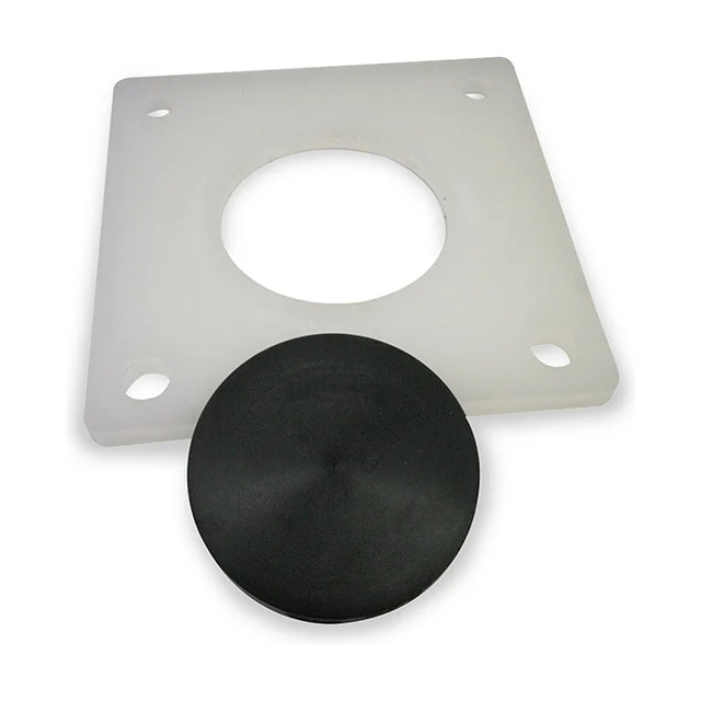
The ATEX kit for the PS: a square, milk-white polypropylene plate with a round hole in the middle and a slotted hole in each corner, and in front of it a black, round tablet with concentric rings in its surface.

The ATEX kit KIT ATEX

If the hammer has to sit in a classified area, it is supplied with an ATEX kit: a polypropylene plate and a WKL tablet. The kit gives category 3D, that is dust zone 22, with temperature class T85 degrees. Note that the category depends on fully pneumatic activation — that is, no coil at the hammer.

MarkingII3D Ex h IIIC T85 °C Dc
Directive2014/34/EU, category 3D
ZoneDust zone 22
ContentsPolypropylene plate and WKL® tablet
ConditionFully pneumatic activation
  1. Category 3D covers dust zone 22, not zone 21 and not zone 20.
  2. The kit depends on the hammer being fired fully pneumatically.
  3. Without the kit the hammer is not marked for classified areas.
  4. We obtain the certificate on the individual order.

How many hammers are needed, where they should sit, and whether it becomes type A or type B depends on the dimensions and angle of the cone, the thickness of the steel, what you handle, and what the compressed air can deliver. Tell us, and we come back with a size, a number and the right version.

Application

Where it sits and what it works in

PlantSilos, hoppers and storage systems
MaterialsAll kinds of powders and granular material, hygroscopic included. Typically flour, detergents, phosphates, fertilizers, lime, cement, clay and pigments
Other dutiesBig-bag emptying and filter cleaning
BenefitsEconomical, low air consumption, efficient, multi-voltage, integrated solenoid valve and timer
SectorsBuilding and construction, food and feed, heavy industries, plastics and chemical processing, recycling and environment technology, and renewable energies
Ex areasWith the ATEX kit: II3D Ex h IIIC T85 °C Dc, that is dust zone 22

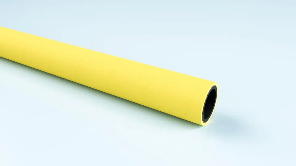
Yellow EPDM compressed air hose, coiled.

FlexCore

ARIACORD/YELLOW

Rugged EPDM hose for compressed air and water, 25 bar. Weather and UV resistant, so it can live outdoors beside the silo.

Material
EPDM
Inner diameter
32–76 mm
Working pressure
25 bar
Temperature
-30 to +80 °C

See the full product page on FlexCore →

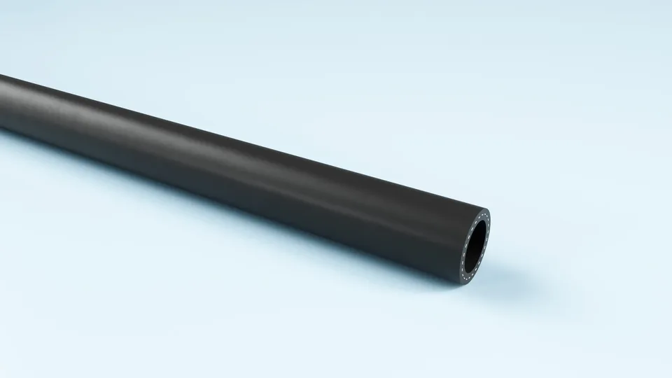
Black TPE air hose, coiled.

FlexCore

ARIAFORM/15

TPE air hose for industry and workshop. Handles water, air and oil-laden compressed air, and is light enough to move around.

Material
TPE
Inner diameter
16–25 mm
Working pressure
15 bar
Temperature
-30 to +80 °C

See the full product page on FlexCore →

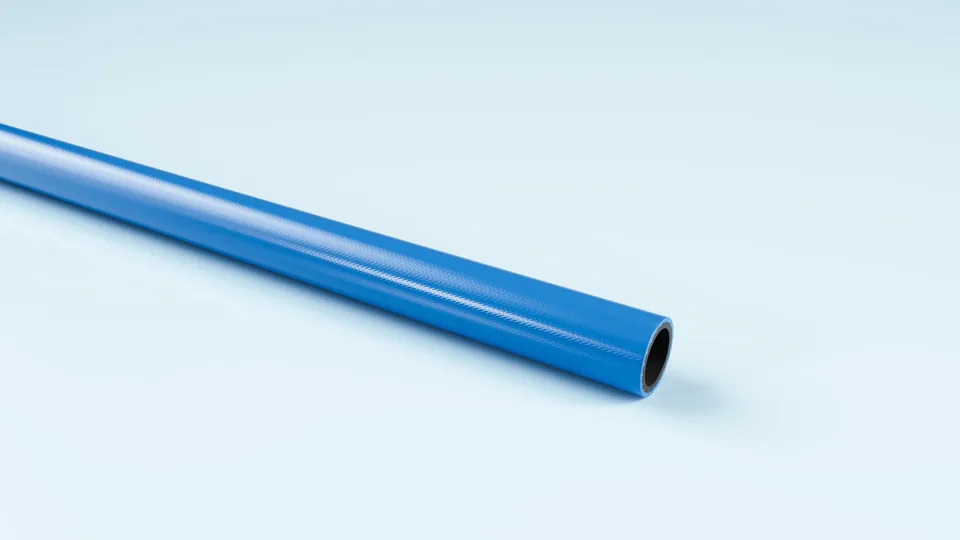
Blue polyurethane hose, coiled.

FlexCore

ARIAFORM/TPU

Light polyurethane hose for tools and reel systems. The softest of the three, where the hose has to follow the work.

Material
TPU
Inner diameter
6–13 mm
Working pressure
20 bar
Temperature
-30 to +80 °C

See the full product page on FlexCore →

Portrait of a technical adviser at Particulair.

Technical advice

Which size, and how thick is the steel?

Tell us the dimensions and angle of the cone, how thick the steel is, what you handle, and what the compressed air can deliver. We come back with a size, a version and a price — not with a catalogue.

Contact us Try the product selector