OLI P · continuous impact vibrators

Continuous impact vibrators for silos, hoppers and chutes

A piston that strikes a welded plate many times a minute. Three sizes from 2.2 to 11 kilos, 2 to 6 bar, 294 to 3,250 newtons, and steel that may be 200 degrees hot.

The material is wet, it sticks, and it stays on the wall no matter how long the air has been on. The P is OLI's vibrator for exactly that situation. Inside the housing a piston runs, driven by compressed air at 2 to 6 bar against a plate welded to the outside of the vessel, and every blow travels on through the steel into the material. It breaks bridges and ratholes, and it takes the build-up that has settled on the wall. The unit sits on the outside, and no hole is drilled in the wall. Three sizes from 2.2 to 11 kilos, and the steel may be as hot as 200 degrees.

P2–6 bar100 dB(A)−20 to 200 °C2.2–11 kg
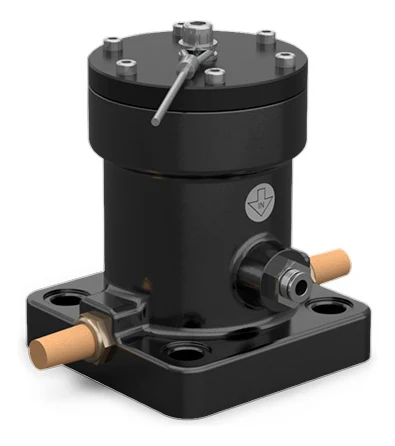
A continuous impact vibrator in the largest version, seen from the front at an angle: a matt black cylinder on an almost square foot with counterbored holes in the corners, a brass silencer on each side, a push-in air connection on the body, and on top a black cover with a ring of bright screws, a hexagonal nut in the middle and a thin rod lying at an angle across the cover.
The problem

Three things that happen to wet material

Bridging and rat-holing are familiar to anyone who has stood at a silo. The third is the one that gets expensive over time: the vessel never empties completely, because a layer stays on the wall that does not come along.

Bridge over the outlet

Bridge over the outlet

The material spans an arch across the opening and carries its own weight. The silo is full, the screw underneath runs in empty space, and nothing moves on.

Rathole through the middle

Rathole through the middle

A narrow shaft runs down through the centre while the rest stands still along the walls. It looks like it is running, but most of it stays put and gets older by the hour.

Incomplete clean out

Incomplete clean out

Wet material sets as a crust on the steel and grows thicker with every filling. The capacity of the vessel shrinks, the last of it never comes along, and in the end somebody has to go in with a bar.

Walkthrough

Four steps through the product

Click through: from the silo the material will not leave, to the decision about ATEX.

01 The problem

The same silo with and without continuous impact vibratorsA silo seen from the side, divided by a vertical line. To the left of the line the material has formed a bridge across the outlet, and under the bridge it is empty; along the two cone walls lies a layer of material that has stayed behind, and nothing comes out at the bottom. To the right, continuous impact vibrators sit on the outside of the cone walls at three heights, each on its own welded plate with the axis perpendicular to the wall. None of them passes through the wall. At each mounting point a star marks where the blow lands, and two arcs spread into the material. The layer is gone, and a stream falls out at the bottom. The line can be dragged from side to side.Without vibratorsWith the P

Without vibrators the material carries its own weight: the bridge stands across the outlet, and a layer stays behind along the cone walls that never comes along. With vibrators the blow travels through the steel and tears the layer off, every single time the piston strikes. It is the same silo on both sides of the line.

02 The technology

Section through a continuous impact vibratorThe vibrator seen in section with the axis horizontal. On the far left the material inside the vessel, then the wall of the vessel, and on the outside of the wall a plate welded at top and bottom. On the plate stands the foot of the vibrator with two bolts, and from the foot the housing extends to the right. Inside the housing there is a bore, and in the bore a piston that runs back and forth and strikes the bottom towards the foot. A star marks the impact, and from the inner face of the wall two arcs spread into the material. The air comes in through a connection at the bottom and leaves through a silencer at the top. The overall height of the unit is dimensioned as A1, the length of the foot as B and the diameter of the housing as Ø G.A1Ø GBThe materialThe wall of the vesselWelded plateThe piston strikes hereOut through the silencerCompressed air inThe cover

The compressed air comes in through the lower port and leaves through the silencer in the upper one. Between the two the piston runs back and forth in the bore and strikes the bottom on every pass. The blow travels on through the foot, the welded plate and the wall into the material. The wall is unbroken: there is no hole.

03 The installation

Continuous impact vibrators on a silo with the whole air supplyA silo seen from the side with continuous impact vibrators bolted onto the outside of the two cone walls at three heights, each on its own welded plate. On the left stands the compressor, and from it an air line runs through four components in a row: a filter, a pressure regulator, a lubricator and a 3/2 way valve. From there the line runs up over the silo and down both sides to each individual vibrator. At each vibrator a star marks where the blow lands, and two arcs spread into the material. At the bottom a stream of material falls out of the outlet.12345

The units mount on the outside of the silo, and no hole is drilled in the wall. That is also why they can go onto a plant that is already running. Four things sit in the supply: a filter, a pressure regulator, a lubricator and a 3/2 way valve.

  1. The compressed air The P runs on compressed air at 2 to 6 bar in continuous duty. The pressure is what sets both the force and the frequency.
  2. The filter The air has to be clean. The filter is the first stage between the compressor and the vibrator.
  3. The pressure regulator It sets the pressure, and on the P the pressure also sets the force and the frequency. If the force has to be changed, this is where it happens.
  4. The lubricator The P wants lubricated air in class 5.4.4. Where oil mist is not allowed at the position, the K comes in an LF version that runs dry.
  5. The units on the silo Everything sits outside, and no hole is drilled in the wall of the vessel. The unit bolts onto a plate welded to the outside, and that plate is what the piston strikes.

04 The choice

With or without the ATEX kit
Version without the ATEX kitThe vibrator drawn in section with the foot on the left on its welded plate, with no marking plate on the body. Below it a temperature scale from minus 20 to 220 degrees with a bar reaching 200 degrees.P without the ATEX kitNo marking, and steel all the way up to 200 degrees.P40-200100200200 °CWorking temperature in degrees celsiusATEX, gasNoneATEX, dustNoneZoneUnclassified areaMaximum steel temperature200 °C
Version with the ATEX kitThe same vibrator drawn at the same size and in the same place, now with a marking plate on the body. Below it the same temperature scale, where the bar reaches only 110 degrees.P with the ATEX kitCategory 2, and the ceiling falls to 110 degrees.P40-200100200110 °CWorking temperature in degrees celsiusATEX, gasII2G Ex h IIB Tx GbATEX, dustII2D Ex h IIIC Tx DbZoneZone 1 and zone 21Maximum steel temperature110 °C

The temperature scale is the same on both sheets, so the difference can be seen and not just read. If you are unsure how the position is classified, tell us what you handle and what the zone is.

Not which size, that is in the table above. The choice you actually face is whether the unit has to sit in a classified area. With the kit it may go into zone 1 and 21, and in return the temperature ceiling falls from 200 to 110 degrees. Click between the two and see what it costs.

The technology

A piston that strikes the steel

Inside the housing runs a piston, and compressed air at 2 to 6 bar drives it against a metal plate welded to the outside of the vessel. Every blow travels through the steel and on into the material. That is what the word impact covers, and it is the whole difference between the P and the cushioned piston vibrators, where the piston never touches the metal. It does cost something: the noise level is 100 dB(A), where the K and the F sit at 80.

The force is chosen with the pressure. The same P40 gives 484 newtons at 2 bar and 1,396 newtons at 6 bar, and the frequency follows from 1,650 to 2,800 vibrations per minute. The working moment, by contrast, is the same at all three pressures on any one model, so it is the pressure alone that moves both force and frequency. The range as a whole runs from 294 to 3,250 newtons. If you need to reach a particular level on a particular wall, tell us what the plate is and we will work it through.

The air has to be lubricated, class 5.4.4. Four things sit in front of the unit: a filter, a pressure regulator, a lubricator and a 3/2 way valve. The regulator is not decoration, because on the P the pressure is also what sets the force. Where oil mist is not allowed at the position, the K in its LF version is the one to look at.

The body is grey cast iron, powder painted, with an aluminium cover, and the working temperature runs from −20 to 200 °C. ATEX is an option and not standard as on the K and the F: with the ATEX kit the P ships in II2G Ex h IIB Tx Gb and II2D Ex h IIIC Tx Db, that is category 2 for zone 1 and zone 21. The kit costs 90 degrees: the ceiling falls from 200 to 110 °C. The letter Tx means the temperature class is not fixed in advance: it follows the installation and has to be agreed before equipment is ordered for a classified area.
Data

Technical specifications

TechnologyPiston impact
Duty cycleContinuous
Working pressure2 to 6 bar
Force294 to 3,250 N, depending on size and pressure
Frequency1,200 to 4,500 vibrations per minute
Air consumption55 to 300 l/min
Pneumatic circuitFilter, pressure regulator, lubricator and 3/2 way valve N.C.
Air supply qualityClass 5.4.4, lubricated
Working temperature−20 to 200 °C. With the ATEX kit: −20 to 110 °C
Noise levelNo more than 100 dB(A)
ATEXII2G Ex h IIB Tx Gb and II2D Ex h IIIC Tx Db, optional with the ATEX kit
MaterialGrey cast iron body, powder painted, and aluminium cover
MountingThe foot bolts onto a plate welded to the outside of the vessel. No hole is drilled in the wall
Weight2.2 to 11 kg
The dimensions

Three sizes

The frequency is given as the span from 2 to 6 bar, because the pressure moves it. The force is given at both ends. A1 is the overall height of the unit and B the length of the foot, and both are dimensioned on the drawing in step 02.

Frequency in vibrations per minute at 2 to 6 bar, force in newtons, working moment in kilogram-centimetres, air consumption in litres per minute, dimensions in millimetres
ModelFrequencyForce 2 barForce 6 barWorking momentAir 2 barAir 6 barA1BWeight
P252,500–4,500294 N954 N0.43 kgcm55 l/min125 l/min98 mm115 mm2.2 kg
P401,650–2,800484 N1,396 N1.63 kgcm70 l/min150 l/min127 mm148 mm4.5 kg
P601,200–1,9001,296 N3,250 N4.11 kgcm100 l/min300 l/min173 mm138 × 142 mm11 kg

The number in the model name follows the size of the housing: the P25 is the smallest and the P60 the largest. A1 is the overall height of the unit and B the length of the foot. The foot changes form with the size: the P25 and P40 have a two lobed foot with two bolts, while the P60 has a square foot with four, which is why B on the P60 is two figures and not one. Ø G is the diameter of the housing, 58, 75 and 115 millimetres. The air inlet is BSPP throughout: 1/4″ on the P25, 3/8″ on the P40 and 1/2″ on the P60. The outlet matches the inlet, except on the P60, which has two. The working moment is the same at all three pressures on any one model.

Components

Two foot shapes, two ports and a cover

It is the same mechanism in all three: a piston that strikes. What changes with the size is the foot, and the foot is what decides what has to be welded onto the vessel. What they all share is that no hole is drilled in the wall.

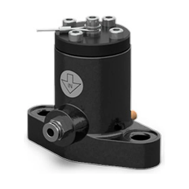
A continuous impact vibrator in one of the two smallest sizes, seen from the front at an angle: a matt black cylinder with an embossed mark on the side, a two lobed black foot with one hole in each lobe, a push-in air connection at the front, and on top a black cover with a ring of bright screws and a thin rod across it.

The two lobed foot P25 · P40

The two smallest sit on two bolts, one in each lobe. The foot is longer along than across: 115 against 70 millimetres on the P25 and 148 against 91 on the P40.

ModelsP25 and P40
Foot length, B115 and 148 mm
Foot width, D70 and 91 mm
Bolt spacing, C85 and 110 mm
Hole diameter, Ø F13 and 17 mm
  1. The P25 weighs 2.2 kilos and has the highest frequency in the range: 4,500 vibrations per minute at 6 bar.
  2. We do not have a tightening torque for the bolts from OLI. If the unit has to sit somewhere where that matters, say so and we will get the figure.
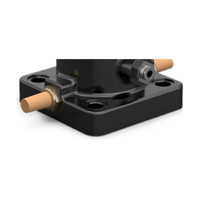
Close-up of the foot of the largest continuous impact vibrator: an almost square black plate with counterbored holes in the corners, a brass silencer on each side, one of them screwed into the foot itself, and the body rising from the middle of the plate.

The square foot P60

The largest sits on four bolts, one in each corner. The foot is almost square, 138 by 142 millimetres, against the elongated foot of the two smaller ones.

ModelP60
Foot dimensions, B138 × 142 mm
Bolt spacing, C99 × 99 mm
Hole diameter, Ø F17 mm
Weight11 kg
  1. The P60 is the strongest in the range: 3,250 newtons at 6 bar, and the only one with two outlets.
  2. The bolt holes are counterbored, so the bolt head does not stand proud of the top of the foot.
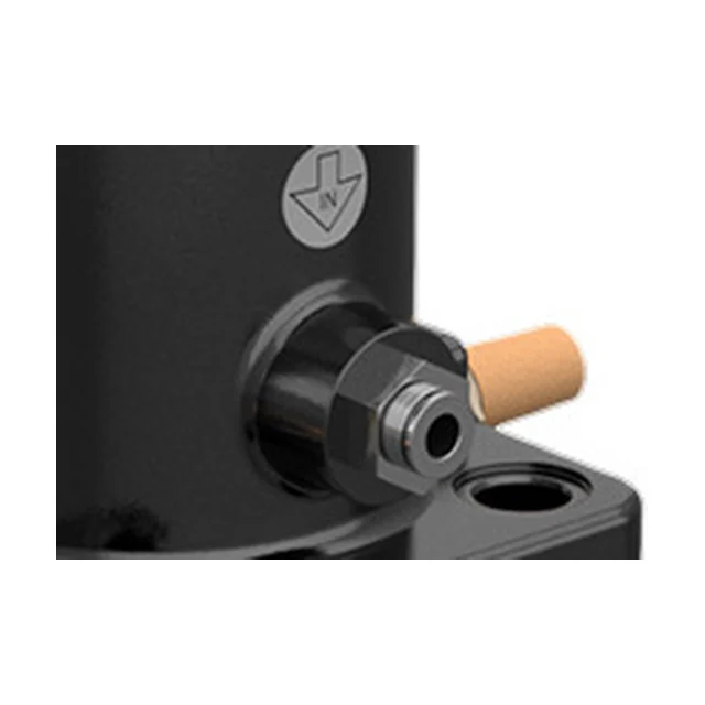
Close-up of the side of the vibrator: a boss on the body with a hexagonal adapter and a push-in fitting for compressed air, a brass sintered silencer right behind it, above them an embossed mark in the housing with an arrow and the letters IN, and at the bottom right one of the holes in the foot.

The inlet and the silencer Alle tre

The two ports sit opposite each other on the circumference. Air comes in through one and leaves through the silencer in the other, and that is the whole circuit inside the housing.

Inlet1/4″, 3/8″ and 1/2″ BSPP
OutletThe same as the inlet
P60Two outlets, both 1/2″ BSPP
Air consumption55 to 300 l/min
  1. Air consumption grows with the pressure: the P40 uses 70 l/min at 2 bar and 150 at 6.
  2. The silencer is the sintered brass part in the outlet. The P60 has two of them.
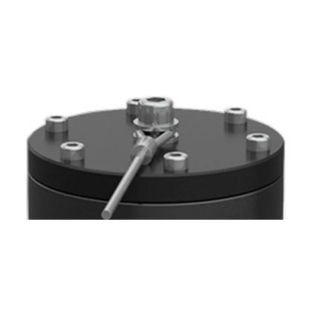
Close-up of the top of the vibrator: a black round cover with a ring of bright screws, a hexagonal nut in the middle, and from the middle a thin rod running at an angle out over the edge of the cover.

The cover and the body Alle tre

The body is grey cast iron and powder painted, and the cover at the far end is aluminium. It is one set of materials across the range, and there is nothing to choose between.

BodyGrey cast iron, powder painted
CoverAluminium
Ø G, housing diameter58, 75 and 115 mm
A1, overall height98, 127 and 173 mm
  1. The cover sits at the end facing away from the vessel. The blow lands at the opposite end, down towards the foot.
  2. Where ATEX is needed, the unit ships with the ATEX kit. The ceiling falls from 200 to 110 degrees at the same time.

What is not a component card here is the plate on the vessel, because it belongs to the wall and not to the vibrator. The foot bolts onto it, and it is welded to the outside so that nothing has to be drilled. Tell us what the vessel is made of and how thick the steel is, and we will come back with the right execution.

Application

Where the P belongs

PlantSilos and hoppers, piping and chutes, salt spreaders, tipper bodies and rail cars
MaterialHygroscopic and humid powders: sludge, aggregates, sand, salt, foundry sand and animal feed
Particularly suited toWet and electrostatic powders, clay, salts and sludges that adhere to the wall, and to thick steel of 10 to 12 millimetres
Typical jobsEmptying silos and hoppers, clearing chutes and piping, unloading tipper bodies and rail cars
Not forDry, fine powder such as cement and lime: there, air underneath the material is the right answer, and then it is bin aerators or fluidisation. Places where 100 dB(A) is too much: the K and the F sit at 80. And a classified area without the ATEX kit, or with the kit and steel above 110 °C.

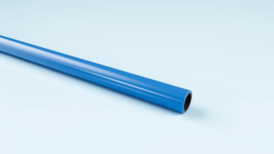
Blue polyurethane hose, coiled.

FlexCore

ARIAFORM/TPU

Light polyurethane hose for tools and reel systems. The softest of the three, where the hose has to follow the work.

Material
TPU
Inner diameter
6–13 mm
Working pressure
20 bar
Temperature
-30 to +80 °C

See the full product page on FlexCore →

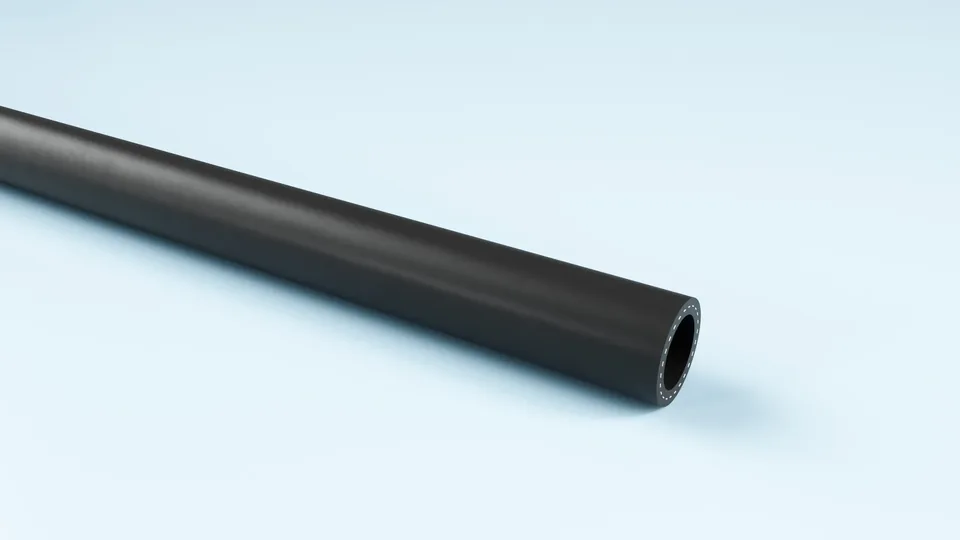
Black TPE air hose, coiled.

FlexCore

ARIAFORM/15

TPE air hose for industry and workshop. Handles water, air and oil-laden compressed air, which is exactly what a P needs.

Material
TPE
Inner diameter
16–25 mm
Working pressure
15 bar
Temperature
-30 to +80 °C

See the full product page on FlexCore →

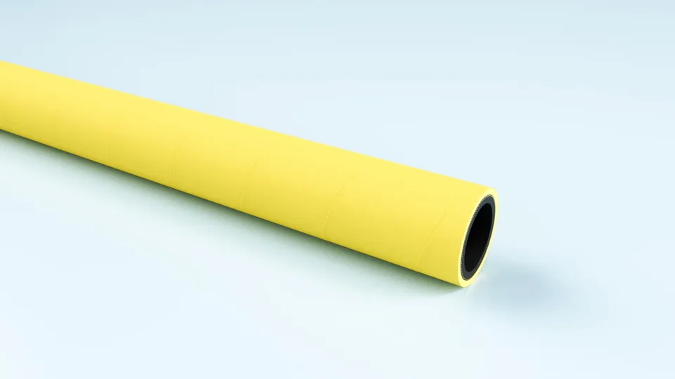
Yellow EPDM compressed air hose, coiled.

FlexCore

ARIACORD/YELLOW

Rugged EPDM hose for compressed air and water, 25 bar. Weather and UV resistant, so it can live outdoors.

Material
EPDM
Inner diameter
32–76 mm
Working pressure
25 bar
Temperature
-30 to +80 °C

See the full product page on FlexCore →

Portrait of a technical adviser at Particulair.

Technical advice

How thick is the steel, and does the unit go into a classified area?

Tell us what the silo, hopper or body is made of, how thick the steel is, what you handle, and whether the position is classified. We come back with a size, a number and a price, not with a catalogue.

Contact us Try the product selector