OLI K · cushioned piston vibrators

Cushioned piston vibrators for silos, hoppers and compacting tables

A floating piston that never reaches the metal. Five sizes from 0.2 to 4.6 kilos, 2 to 6 bar, no more than 80 dB(A), and the whole range is also available lubrication free.

The material stands still in the silo, in the throat of the hopper or on the table, and a blow would be too much: the plate is thin, the grains must not be crushed, or somebody is working next to it. The K is OLI's vibrator for exactly that situation. Compressed air at 2 to 6 bar drives a piston up and down inside a bore, and air is left at both ends so it never reaches the metal. That is why the noise stays below 80 dB(A), and why there is no impact to wear out. The unit mounts on the outside, and no hole is drilled in the wall. Five sizes from 0.2 to 4.6 kilos, and every one of them comes in a version that runs on dry air with no lubricator.

K2–6 bar80 dB(A)−20 to 130 °C0.2–4.6 kg
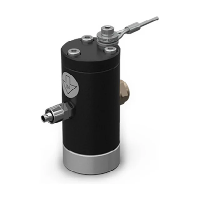
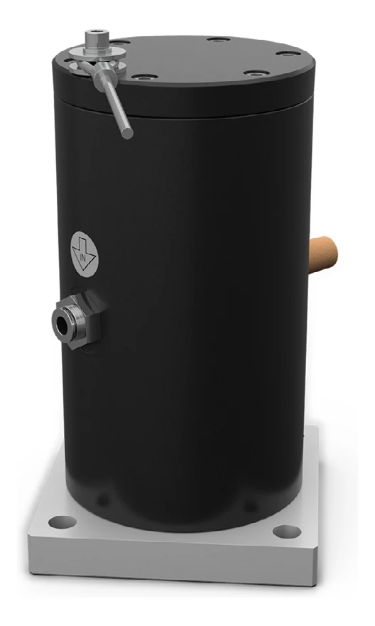
A cushioned piston vibrator in the flange mounted version, seen from the front at an angle: a matt black cylinder with a black cover on top, a brass silencer and a steel air connection on the side, a square aluminium flange with four holes at the bottom, and on top a threaded stud with a thin rod.
The problem

Two things the material does, and two you need done

Bridging and rat-holing are familiar to anyone who has stood at a silo. What sets the K and the F apart from the rest of the range is the next two: loosening what has already set, and compacting powder where that is the point.

Bridge over the outlet

Bridge over the outlet

The material spans an arch across the opening and carries its own weight. The silo is full, the screw underneath runs in empty space, and nothing moves on.

Rathole through the middle

Rathole through the middle

A narrow shaft runs down through the centre while the rest stands still along the walls. It looks like it is running, but most of it stays put and gets older by the hour.

Detaching and compacting

Detaching and compacting

A layer that has set on the steel has to be shaken free without damaging the plate, and powder in a mould or on a table has to be compacted evenly without crushing the grains. Compacting is the K's and the F's own job in the range.

Walkthrough

Four steps through the product

Click through: from the silo the material will not leave, to the choice between lubricated and lubrication free.

01 The problem

The same silo with and without cushioned piston vibratorsA silo seen from the side, divided by a vertical line. To the left of the line the material has formed a bridge across the outlet, and under the bridge it is empty; along the two cone walls lies a layer of material that has stayed behind, and nothing comes out at the bottom. To the right, piston vibrators sit on the outside of the cone walls at three heights, bolted on with the axis perpendicular to the wall. None of them passes through the wall. From each mounting point a double arrow shows the direction of the vibration, and two arcs spread into the material. The layer is gone, and a stream falls out at the bottom. The line can be dragged from side to side.Without vibratorsWith the K

Without vibrators the material carries its own weight: the bridge stands across the outlet, and a layer stays behind along the cone walls that never comes along. With vibrators the vibration travels through the steel and keeps the material moving all the way down. It is the same silo on both sides of the line.

02 The technology

Section through a cushioned piston vibratorThe vibrator seen in section with the axis horizontal. On the left the mounting face with the thread the unit hangs in. On the right the housing with a bore, and inside the bore a piston lying free. At each end of the bore three arcs are drawn, showing the cushion of air the piston does not get through. A double arrow through the piston shows that it runs back and forth. The air comes in through a connection at the bottom and leaves through a silencer at the top, at the same distance from the end face. The overall length of the housing is dimensioned as B, its diameter as Ø A, the distance of the ports from the end face as C and D, and the M dimension at the end face.BØ AMAir cushionFloating pistonOut through the silencerCompressed air inThread, G

The compressed air comes in through the lower port and leaves through the silencer in the upper one. Between the two the piston runs back and forth in the bore, and at each end there is a cushion of air it does not get through. There is no metal-on-metal impact, and that is why it stays below 80 dB(A). On the left sits the thread the unit hangs in.

03 The installation

Cushioned piston vibrators on a silo with the whole air supplyA silo seen from the side with piston vibrators bolted onto the outside of the two cone walls at three heights. On the left stands the compressor, and from it an air line runs through four components in a row: a filter, a flow control valve, a lubricator drawn with a dashed outline, and a 3/2 way valve. From there the line runs up over the silo and down both sides to each individual vibrator. From each vibrator a double arrow shows the direction of the vibration into the wall, and two arcs spread into the material. At the bottom a stream of material falls out of the outlet.12345

The units mount on the outside of the silo, and no hole is drilled in the wall. That is also why they can go onto a plant that is already running. In the supply sit a filter, a flow control valve, a lubricator and a 3/2 way valve. The dashed lubricator is the one that falls away on the lubrication free version.

  1. The compressed air The K runs on compressed air at 2 to 6 bar in continuous duty. The pressure is what sets both the force and the frequency.
  2. The filter The air has to be clean. The filter is the first stage between the compressor and the vibrator, and it is there on both versions.
  3. The lubricator This is what separates the two versions. The standard K wants lubricated air in class 5.4.4. Where oil mist is not allowed at the position, the whole range comes in an LF version that runs dry on class 5.4.1.
  4. The 3/2 way valve The valve is normally closed and opens the air when the vibrator is to run. It is the last stage before the connection.
  5. The units on the silo Everything sits outside, and no hole is drilled in the wall of the vessel. That is why the range can also go onto a plant that already stands finished. The vibration runs through the steel and on into the material.

04 The choice

Lubricated or lubrication free
Version K, the circuit with a lubricatorThe circuit drawn from left to right: the compressor, then four boxes in a row, which are the filter, the flow control valve, the lubricator and the 3/2 way valve, and finally an air line down to the vibrator, which is drawn with the axis horizontal and the mounting face on the left.K, lubricated airFour components in the supply, and oil mist in the air.Compressed airFilterFlow valveLubricator3/2 valveK 30Air qualityClass 5.4.4, lubricatedCircuitFour componentsForce, K 22 at 6 bar191.5 NWorking moment, K 220.21 kgcm
Version K-LF, the circuit without a lubricatorThe same circuit with one box fewer: the compressor, then three boxes in a row, which are the filter, the flow control valve and the 3/2 way valve, and finally an air line down to the vibrator, which is drawn with the axis horizontal and the mounting face on the left.K-LF, no lubricationThree components. The lubricator falls away.Compressed airFilterFlow valve3/2 valveK 30Air qualityClass 5.4.1, dryCircuitThree componentsForce, K 22 at 6 bar164.1 NWorking moment, K 220.18 kgcm

The circuit is drawn to the same scale on both sheets so the difference can be seen. If you are unsure what is possible where the unit has to sit, tell us what the air comes from and what you handle.

Not which size, that is in the table above. The choice you actually face is whether oil mist may be present in the air where the unit has to sit. On a feed or food installation the answer is no, and then it is the LF. Click between the two: the circuit differs, and on three of the five sizes so does the force.

The technology

A piston that stops in air

Inside the housing there is a bore, and inside the bore lies a floating piston. Compressed air at 2 to 6 bar drives it up and down, and air is left at both ends so it never makes metal-on-metal contact. That is what the word cushioned covers, and it is the whole difference between a vibrator and a hammer. That is why the noise stays below 80 dB(A), where a pneumatic hammer sits at 125. The vibration does not travel through the air to the material; it travels through whatever the housing is bolted to: the silo wall, the hopper or the table.

The force is chosen with the pressure. The same K 30 gives 171.8 newtons at 2 bar and 341.1 newtons at 6 bar, and the frequency follows from 2,640 to 3,720 vibrations per minute. The working moment, by contrast, is the same at all three pressures on any one model, so it is the pressure alone that moves both force and frequency. If you need to reach a particular level on a particular wall, tell us what the plate is and we will work it through.

The range comes in two versions, and that is the decision to take before ordering. The standard K wants lubricated air: a filter, a flow control valve, a lubricator and a 3/2 way valve in front, and air in class 5.4.4. The K-LF runs without lubrication on dry air in class 5.4.1, the same quality as the rest of the range. The whole range comes in the lubrication free version, and the force is different on three of the five sizes. The figures are in step 04.

The housing is aluminium with an Ixef® cover, and the working temperature runs from −20 to 130 °C. Where the plate is hotter, the F or the P are the ones to look at. ATEX is not an option: the K ships as standard in II2G Ex h IIB Tx Gb and II2D Ex h IIIC Tx Db, that is category 2 for zone 1 and zone 21. The letter Tx means the temperature class is not fixed in advance: it follows the installation and has to be agreed before equipment is ordered for a classified area.
Data

Technical specifications

TechnologyPiston cushioned
Duty cycleContinuous
Working pressure2 to 6 bar
Force33.4 to 2,123.7 N, depending on size and pressure
Frequency1,260 to 6,720 vibrations per minute
Air consumption9 to 202 l/min
Pneumatic circuitK: filter, flow control valve, lubricator and 3/2 way valve N.C. K-LF: the same without the lubricator
Air supply qualityK: class 5.4.4, lubricated. K-LF: class 5.4.1, dry
Working temperature−20 to 130 °C
Noise levelNo more than 80 dB(A)
ATEXII2G Ex h IIB Tx Gb and II2D Ex h IIIC Tx Db, as standard
MaterialAluminium body and Ixef® cover
MountingK 15, K 22 and K 30: a thread in the end face, M8, M10 or M12. K 45 and K 60: a square flange with four holes
Weight0.2 to 4.6 kg
The dimensions

Five sizes in two versions

The frequency is given as the span from 2 to 6 bar, because the pressure moves it. The force is given at both ends. LF is the lubrication free version. Ø A is the diameter of the housing and B its overall length, and both are dimensioned on the drawing in step 02.

Frequency in vibrations per minute at 2 to 6 bar, force in newtons, working moment in kilogram-centimetres, air consumption in litres per minute, dimensions in millimetres
ModelFrequencyForce 2 barForce 6 barWorking momentAir 2 barAir 6 barØ ABWeight
K 155,040–6,72033.4 N59.4 N0.02 kgcm9 l/min21 l/min32 mm69 mm0.2 kg
K 15 LF5,040–6,72033.4 N59.4 N0.02 kgcm9 l/min21 l/min32 mm69 mm0.2 kg
K 222,880–4,08095.4 N191.5 N0.21 kgcm32 l/min73 l/min45 mm105 mm0.5 kg
K 22 LF2,880–4,08081.8 N164.1 N0.18 kgcm32 l/min73 l/min45 mm105 mm0.5 kg
K 302,640–3,720171.8 N341.1 N0.45 kgcm45 l/min140 l/min60 mm116 mm1.0 kg
K 30 LF2,640–3,720160.3 N318.4 N0.42 kgcm45 l/min140 l/min60 mm116 mm1.0 kg
K 451,920–2,580390.9 N705.9 N1.94 kgcm56 l/min194 l/min80 mm151 mm2.9 kg
K 45 LF1,920–2,580394.2 N711.7 N1.95 kgcm56 l/min194 l/min80 mm151 mm2.9 kg
K 601,260–2,160722.6 N2,123.7 N8.31 kgcm70 l/min202 l/min115 mm224 mm4.6 kg
K 60 LF1,260–2,160722.6 N2,123.7 N8.31 kgcm70 l/min202 l/min115 mm224 mm4.6 kg

The number in the model name follows the size of the housing: the K 15 is the smallest and the K 60 the largest. LF is the lubrication free version, and the two in each pair share dimensions and weight. Ø A is the diameter of the housing and B its overall length. The air inlet is M5 on the K 15 and BSPP on all the others: 1/8″ on the K 22, 1/4″ on the K 30 and K 45 and 1/2″ on the K 60. The outlet matches the inlet except on two: the K 15 has 1/8″ BSPP out, and the K 45 has 3/8″. The mounting changes form with the size: the K 15, K 22 and K 30 hang in a thread in the end face, M8, M10 or M12, while the K 45 and K 60 have a square flange with four through holes of 8.5 and 13 millimetres. The working moment is the same at all three pressures on any one model.

Components

Two ways to hang it, and two ports

It is the same mechanism in all five: a floating piston in a bore. What changes with the size is how the unit is fixed. What they all share is that no hole is drilled in the wall.

A cushioned piston vibrator on a square aluminium flange, seen from the front at an angle: a matt black cylinder with a black cover on top, a brass silencer and a steel air connection on the side, four holes in the corners of the flange, and on top a threaded stud with a thin rod.

The flange K 45 · K 60

The two largest hang in a square flange with four through holes. The flange sits against whatever it is bolted to, and the body stands perpendicular to that face.

ModelsK 45 and K 60
Flange side, L90 and 130 mm
Hole spacing, H72 and 102 mm
Hole diameter, Ø G8.5 and 13 mm
Flange thickness, M15 and 20 mm
  1. The K 60 is the strongest in the range: 2,123.7 newtons at 6 bar.
  2. The flange is part of dimension B, which is therefore the overall length of the housing including it.
A cushioned piston vibrator without a flange, seen from the front at an angle: a matt black cylinder with a black cover on top and a bright aluminium ring at the bottom, a brass silencer and a steel air connection on the side, and on top a threaded stud with a thin rod.

The thread in the end face K 15 · K 22 · K 30

The three smallest have no flange. They hang in a single thread in the middle of the end face, and that is also what makes them so small: there is no plate to make room for.

ModelsK 15, K 22 and K 30
Thread, GM8, M10 and M12
Ø A32, 45 and 60 mm
The M dimension at the end face9, 13 and 13 mm
Weight0.2, 0.5 and 1.0 kg
  1. The K 15 weighs 200 grams and has the highest frequency in the range: 6,720 vibrations per minute at 6 bar.
  2. We do not have a tightening torque for the thread from OLI. If the unit has to sit somewhere where that matters, say so and we will get the figure.
The smallest cushioned piston vibrator, seen from the front at an angle: a matt black cylinder with a black cover on top and a bright aluminium ring at the bottom, a brass hexagonal silencer on one side, a steel air connection on the other, and on top a threaded stud with a thin rod.

The inlet and the silencer Alle fem

The two ports sit opposite each other on the circumference, at the same height. Air comes in through one and leaves through the silencer in the other, and that is the whole circuit inside the housing.

Inlet, EM5 on the K 15, otherwise BSPP
Outlet, F1/8″ to 1/2″ BSPP
Distance from the end face, C and D37 to 115 mm
Air consumption9 to 202 l/min
  1. The two ports sit the same distance from the end face on every model. C and D are the same figure throughout.
  2. Air consumption is identical for the two versions of each size. It is the force and the working moment that change.

What is not a component card here is the circuit in front of the unit, because that is not a part but a decision. The standard K wants a filter, a flow control valve, a lubricator and a 3/2 way valve, while the K-LF manages with the three without the lubricator. The choice is in step 04.

Application

Where the K belongs

PlantSilos and hoppers, pipes, tanks, compacting, vibrating feeders, tables and channels
MaterialHygroscopic or dusty powders and granules: animal feed, aggregates, plastics and foods
Particularly suited toCoarse grained hygroscopic materials and electrostatic powders in the plastics and recycling sector, which tend to adhere to the inner wall
Typical jobsEmptying silos and hoppers, big bag emptier, compacting table for powders, filter bag cleaning, pipes and chutes
SectorsBuilding and construction, food and feed, heavy industry, machinery and plant, plastics and chemicals, recycling and environmental technology, renewable energy
Not forPlate above 130 °C: the K does not reach that, and then it is the F or the P. A classified area without an agreed temperature class. And where the material has set hard under pressure and needs a real blow, the pneumatic hammers or the P do the work.

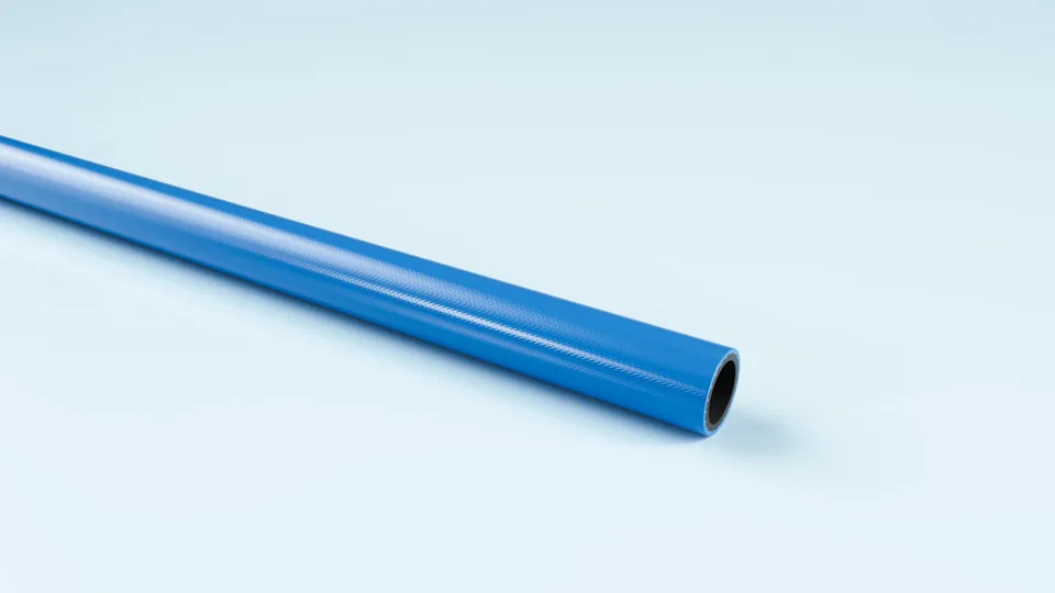
Blue polyurethane hose, coiled.

FlexCore

ARIAFORM/TPU

Light polyurethane hose for tools and reel systems. The softest of the three, where the hose has to follow the work.

Material
TPU
Inner diameter
6–13 mm
Working pressure
20 bar
Temperature
-30 to +80 °C

See the full product page on FlexCore →

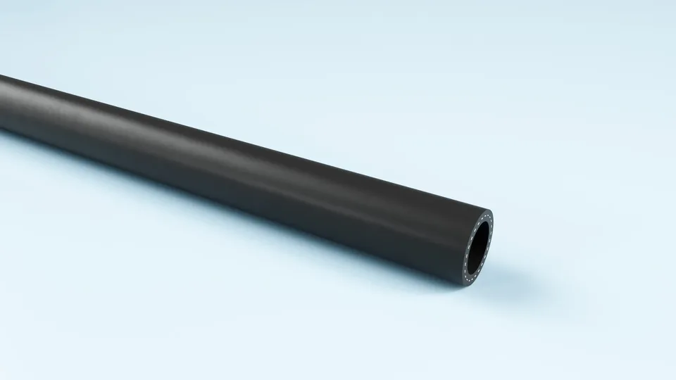
Black TPE air hose, coiled.

FlexCore

ARIAFORM/15

TPE air hose for industry and workshop. Handles water, air and oil-laden compressed air, which is exactly what a standard K needs.

Material
TPE
Inner diameter
16–25 mm
Working pressure
15 bar
Temperature
-30 to +80 °C

See the full product page on FlexCore →

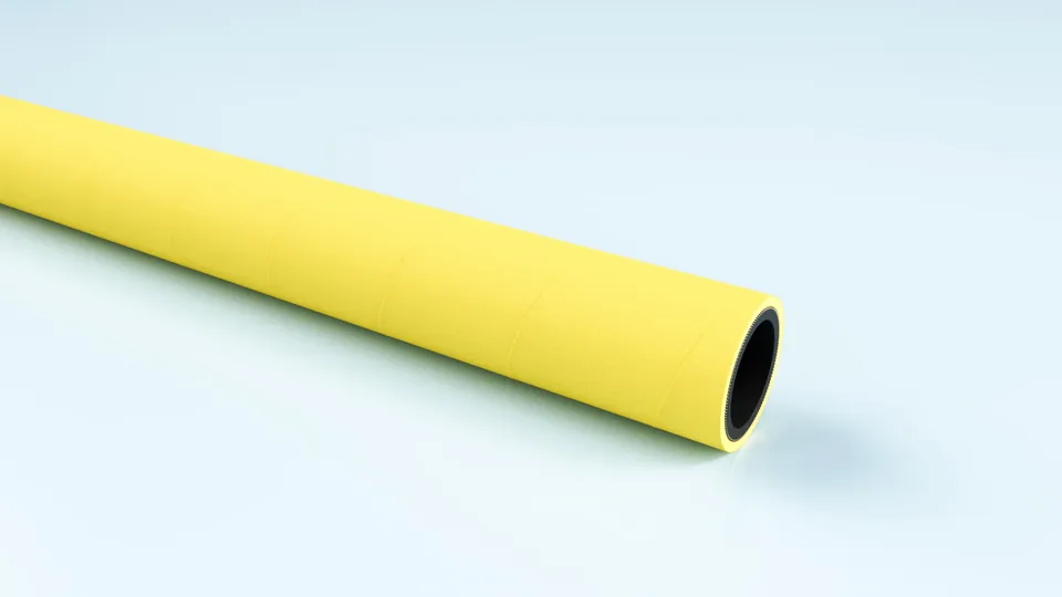
Yellow EPDM compressed air hose, coiled.

FlexCore

ARIACORD/YELLOW

Rugged EPDM hose for compressed air and water, 25 bar. Weather and UV resistant, so it can live outdoors.

Material
EPDM
Inner diameter
32–76 mm
Working pressure
25 bar
Temperature
-30 to +80 °C

See the full product page on FlexCore →

Portrait of a technical adviser at Particulair.

Technical advice

Which size, and may the air be lubricated?

Tell us what the silo or hopper is made of, how thick the steel is, what you handle, and whether oil mist may occur where the unit has to sit. We come back with a size, a version and a price, not with a catalogue.

Contact us Try the product selector