OLI OT · turbine vibrators

Turbine vibrators for dry material and food

A turbine with integrated masses turning in bearings. Twelve models in four sizes, 2 to 6 bar, up to 781 kilos of centrifugal force, unlubricated air and ATEX category 2 as standard.

Sugar, bicarbonate, phosphate and sodium are dry and granular, and they have to leave the silo without picking up oil. The OT is OLI's turbine vibrator for exactly that. Compressed air at 2 to 6 bar drives a turbine with integrated masses round in bearings, and the air does not have to be lubricated: the circuit is a filter, a flow control valve and a valve, and nothing else. The unit bolts on the outside, and no hole is drilled in the wall. Twelve models from 250 grams to 2.5 kilos, all with ATEX category 2 for both gas and dust.

OT2–6 bar<90 dB(A)−20 to 120 °C0.25–2.53 kg
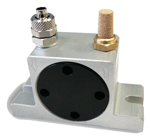
A turbine vibrator seen from the front at an angle: a light aluminium body, clearly wider than it is tall, with a large round black cover in the middle of the side. Four through holes sit near the rim of the cover. On top are two connections: on the left a metal push-in fitting, on the right a brass nut carrying a sintered bronze silencer. An arrow is cast into the front face under each connection: on the left an arrow pointing down, on the right an arrow pointing up. At the bottom the body meets a wide foot with an open slot in the end.
The problem

Two everybody knows, and two that belong to the rotary range

Bridging and rat-holing are familiar to anyone who has stood at a silo. What sets the rotary range apart from the rest of the programme is what comes next: reducing the friction between the material and the steel, separating material that has lumped together, and packing it down where that is what is wanted. The last one belongs to the OT alone.

Bridge over the outlet

Bridge over the outlet

The material spans an arch across the opening and carries its own weight. The silo is full, the screw underneath runs in empty space, and nothing moves on.

Rathole through the middle

Rathole through the middle

A narrow shaft runs down through the centre while the rest stands still along the walls. It looks like it is running, but most of it stays put and gets older by the hour.

Friction and separation

Friction and separation

Fine powders stick to the steel instead of sliding, and they lump together instead of falling apart. A high frequency works exactly there, in the boundary between the material and the surface.

Consolidation

Consolidation

Sometimes the job is the other way round: the material has to pack down, not loosen up. Concrete in a mould has to settle tight, without air pockets and without pores in the surface. It is the only one of the rotary range documented for that.

Walkthrough

Four steps through the product

Click through: from the silo the material will not leave, to the choice between the three models in one size.

01 The problem

The same silo with and without turbine vibratorsA silo seen from the side, divided by a vertical line. To the left of the line the material has formed a bridge across the outlet, and under the bridge it is empty; along the two cone walls a layer of material has stayed behind, and nothing comes out at the bottom. To the right turbine vibrators sit on the outside of the cone walls at three heights, bolted on with the foot against the wall. None of them goes through the wall. At each unit a circular arrow shows that the force rotates, and two arcs spread into the material. The layer is gone, and a stream falls out at the bottom. The line can be dragged from side to side.Without vibratorsWith the OT

Without vibrators the material carries its own weight: the bridge stands across the outlet, and a layer stays behind along the cone walls that never comes along. With vibrators the vibration travels through the steel and keeps the material moving all the way down. It is the same silo on both sides of the line.

02 The technology

Section through a turbine vibrator, and the foot seen from belowAbove, the vibrator seen from the front in section. The body is slightly wider than it is tall and stands on a wider foot. Inside the body is a circular bore, and at the outer edge of the bore lies a ring. Inside the ring a turbine turns: five equal round masses spaced unevenly about the centre, and between them a bearing of two concentric rings. Two ports sit in the top face of the body: the air comes in through the left one and leaves through the right. The width of the body and the overall height of the unit are both dimensioned as A, and the thickness of the foot as D. Below is the foot seen from underneath: an elongated plate with an open slot at each end and two round holes inboard. The length of the foot is dimensioned as B, the distance between the slots as C, the depth of the foot as E and the width of the slot as F.AADCompressed air inAir outThe turbineThe bearingThe foot from belowBCEFOT20

The compressed air comes in through the left port and out through the right. Between the two a turbine with five integrated masses turns. The masses are the same size, but they are not evenly spaced, and that is why the centre of gravity lies off the axis. In the middle sits the bearing, and that is what separates the turbine from the ball and the roller: it does not run free in a track, it turns about a fixed axis. Below is the foot seen from underneath. The drawing shows that the turbine turns, not how fast: a real OT20 reaches 242 to 383 revolutions per second.

03 The installation

Turbine vibrators on a silo with the complete air supplyA silo seen from the side with turbine vibrators bolted to the outside of the two cone walls at three heights. On the left stands the compressor, and from it an air line runs through three components in a row: a filter, a flow control valve and a 3/2 way valve. There is no lubricator. From there the line goes up over the silo and down both sides to each vibrator. At each vibrator a circular arrow shows that the force rotates, and two arcs spread into the material. At the bottom a stream of material falls out of the outlet.12345

The units bolt to the outside of the silo, and no hole is drilled in the wall. That is also why they can go onto a plant that is already running. In the supply sit a filter, a flow control valve and a 3/2 way valve. There is no lubricator: the OT runs on unlubricated air in class 5.4.1.

  1. The compressed air The OT runs on compressed air at 2 to 6 bar. The pressure is what sets the frequency, the force and the air consumption alike.
  2. The filter The air has to be clean. The filter is the first stage between the compressor and the vibrator, and it is there on all twelve models.
  3. The flow control valve The valve sets the quantity of air and with it how hard the unit works. It is the second and last conditioning stage: no lubricator follows it, as it does on the ball and roller vibrators.
  4. The 3/2 way valve The valve is normally closed and opens the air when the vibrator is to run. It is the last stage before the connection, and it is also what controls how long it runs at a time.
  5. The units on the silo The foot bolts to the outside, and no hole is drilled in the wall of the vessel. The force is rotary and not linear, which is why the symbol is a circular arrow and not a double arrow.

04 The choice

The model within one size
The OT20 at 6 bar with the three figuresA turbine vibrator seen from the front in section with the turbine and the bearing, and below it three horizontal bars drawn to the same fixed scale: vibrations per minute, centrifugal force and air consumption for the OT20 at 6 bar.OT20All three in the same body, at 6 bar.A 80 mmVibrations per minute23,000Centrifugal force526 kgAir consumption452 l/min
The OT25 at 6 bar with the three figuresA turbine vibrator seen from the front in section with the turbine and the bearing, and below it three horizontal bars drawn to the same fixed scale: vibrations per minute, centrifugal force and air consumption for the OT25 at 6 bar.OT25All three in the same body, at 6 bar.A 80 mmVibrations per minute17,000Centrifugal force508 kgAir consumption452 l/min
The OT25S at 6 bar with the three figuresA turbine vibrator seen from the front in section with the turbine and the bearing, and below it three horizontal bars drawn to the same fixed scale: vibrations per minute, centrifugal force and air consumption for the OT25S at 6 bar.OT25SAll three in the same body, at 6 bar.A 80 mmVibrations per minute13,500Centrifugal force483 kgAir consumption452 l/min

The figures are the 80 mm size's at 6 bar, that is the size shown on the drawing in step 02. The bars are drawn to the same fixed scale on all three sheets, so the difference can be seen as a length. The speed falls the same way in the other three sizes, but the figures are not the same: look your own up in the table above.

The size follows from the room available, and the dimensions are in the table above. What actually has to be chosen is which of the three models in that size you take. They share the dimensions and use exactly the same air: the air bar is the same on all three sheets. What changes is the speed, and it falls from the first to the last in all four sizes.

The technology

A turbine with integrated masses turning in bearings

Inside the body sits a turbine with integrated masses. Compressed air at 2 to 6 bar drives it round, and the masses are not evenly spaced: that is why the centre of gravity lies off the axis, and why the rotation produces a force. This is where the OT differs from the ball and roller vibrators. The ball and the roller run free in a hardened track, while the turbine sits in bearings and turns about a fixed axis.

That allows a high rotational speed. An OT8 reaches 42,000 vibrations per minute at 6 bar, and that is the highest figure in the whole programme: no other vibrator gets there. The largest, the OT30, gives 781 kilos of centrifugal force at the same pressure. The noise stays below 90 dB(A), and the temperature limit is 120 °C.

The air does not have to be lubricated. The OT is the only one of the three rotary ranges running on class 5.4.1, so the circuit is three stages instead of four: a filter, a flow control valve and a 3/2 way valve. No oil mist leaves the exhaust, and that is what makes the range usable on sugar, bicarbonate, phosphate and sodium. The body is aluminium, the range has twelve models in four sizes from 250 grams to 2.5 kilos, and all twelve carry ATEX category 2 for both gas and dust as standard. The duty is discontinuous. If the unit has to run without stopping, tell us for how long at a time and we will find the right answer.
Data

Technical specifications

TechnologyTurbine vibration, high frequency and centrifugal force
Duty cycleDiscontinuous
Working pressure2 to 6 bar
Centrifugal force72 to 781 kg, depending on model and pressure
Frequency6,000 to 42,000 vibrations per minute
Air consumption45 to 749 l/min
Pneumatic circuitFilter, flow control valve and 3/2 way valve N.C.
Air supply qualityClass 5.4.1, unlubricated
Working temperature−20 to 120 °C
Noise levelBelow 90 dB(A)
ATEXII2G Ex h IIB Tx Gb and II2D Ex h IIIC Tx Db, as standard
MaterialAluminium body
MountingFoot with four fixing points, bolted on the outside
Connection1/8″, 1/4″ or 3/8″ BSPP, the same in and out
Weight0.25 to 2.53 kg
The dimensions

Twelve models in four sizes

The frequency is given as the span from 2 to 6 bar, because the pressure moves it. The force is given at both ends. A is the width of the body and its overall height including the foot, B is the length of the foot, and both are dimensioned on the drawing in step 02. The three models in one size share every dimension and the whole air consumption.

Frequency in vibrations per minute at 2 to 6 bar, centrifugal force in kilograms, air consumption in litres per minute, dimensions in millimetres
ModelFrequencyForce 2 barForce 6 barAir 2 barAir 6 barABConnectionWeight
OT834,000–42,000110 kg292 kg45 l/min110 l/min50 mm86 mm1/8″ BSPP0.25 kg
OT1026,000–38,000105 kg252 kg45 l/min110 l/min50 mm86 mm1/8″ BSPP0.26 kg
OT10S17,200–26,00072 kg187 kg45 l/min110 l/min50 mm86 mm1/8″ BSPP0.26 kg
OT1324,500–31,000202 kg300 kg122 l/min285 l/min65 mm113 mm1/4″ BSPP0.57 kg
OT1618,000–21,000194 kg264 kg122 l/min285 l/min65 mm113 mm1/4″ BSPP0.58 kg
OT16S11,500–17,500129 kg234 kg122 l/min285 l/min65 mm113 mm1/4″ BSPP0.61 kg
OT2014,500–23,000251 kg526 kg184 l/min452 l/min80 mm128 mm1/4″ BSPP1.09 kg
OT2513,200–17,000244 kg508 kg184 l/min452 l/min80 mm128 mm1/4″ BSPP1.12 kg
OT25S9,000–13,500214 kg483 kg184 l/min452 l/min80 mm128 mm1/4″ BSPP1.20 kg
OT3011,000–14,500351 kg781 kg322 l/min749 l/min100 mm160 mm3/8″ BSPP2.20 kg
OT368,500–12,000341 kg749 kg322 l/min749 l/min100 mm160 mm3/8″ BSPP2.30 kg
OT36S6,000–8,500406 kg754 kg322 l/min749 l/min100 mm160 mm3/8″ BSPP2.53 kg

The number in the model name rises with the force and falls with the speed. The width of the body is A, which is also the overall height of the unit including the foot; B is the length of the foot. Both are dimensioned on the drawing in step 02, and the four remaining letters appear both on the drawing and as figures on the component card: C is the distance between the two slots, D the thickness of the foot, E its depth and F the width of the slot. The twelve models fall into four body sizes with three in each, and the three share all six dimensions, the thread and the whole air consumption. The models with an S after the number run more slowly than the other two in the same size. If you need a particular combination of speed and force, tell us and we will find the right one of the three. The connection is a BSPP thread of the same size in and out, and the force is the maximum centrifugal force, given in kilograms.

Components

Four things worth looking at before ordering

It is the same mechanism in all twelve: a turbine in bearings. What changes with the size is the dimensions and the thread. What they all share is that no hole is drilled in the wall.

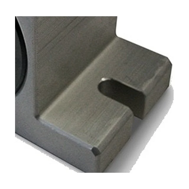
Close-up of one end of the foot on a turbine vibrator, seen from above at an angle. An elongated slot with a rounded end lies in the top face of the foot and opens out towards its edge. On the left is the edge of the black cover. The material is untreated aluminium with visible machining marks.

The foot A · B · C · D · E · F

The foot has four fixing points, not two. The two outer ones are open slots running out to the end, and the two inner ones are round holes. The foot lies against whatever it is bolted to, and the body stands up at right angles to it. It is deeper than on the ball and roller vibrators, because the turbine and the bearings need the room.

Foot length, B86 to 160 mm
Slot spacing, C68 to 130 mm
Foot thickness, D12, 16 and 20 mm
Foot depth, E33 to 73 mm
Slot width, F7, 9 and 11 mm
  1. An open slot means the unit can be dropped over two bolts that are already in place and tightened without taking them out.
  2. No hole is drilled in the wall of the vessel.
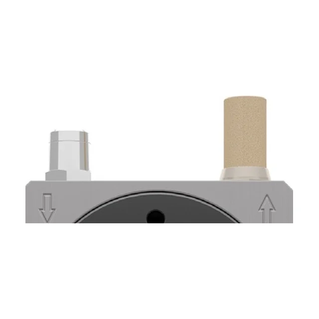
The top of a turbine vibrator seen from the front: two connections on the top face of the body. On the left a short cylindrical spigot, on the right a brass nut carrying a sintered bronze silencer. An arrow is cast into the front face under each connection: on the left an arrow pointing down and on the right an arrow pointing up. At the bottom of the picture is the top edge of the black cover with one of its four holes.

The connections IN · OUT

There are two ports in the top face. The air comes in through one and leaves through the other, and the thread is the same at both ends. A silencer sits on the exhaust. The two cast arrows in the front face sit one under each port.

The three smallest1/8″ BSPP
The six in the middle1/4″ BSPP
The three largest3/8″ BSPP
Air supply qualityClass 5.4.1, unlubricated
  1. The thread is the same in and out on all twelve models.
  2. If you need fittings, tell us and we will confirm which port is the inlet and which is the outlet.
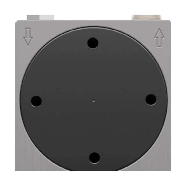
The front of a turbine vibrator: a large round black cover filling nearly the whole front face of the body. Four through holes sit near the rim of the cover, one at the top, one at the bottom and one on each side, and a small mark sits at its centre. To the left and right of the cover an arrow is cast into the front face.

The cover Ø 0,9 A

The cover closes the bore the turbine sits in, and it therefore fills nearly the whole front face: the diameter of the bore is a good nine tenths of the width of the body. The four holes sit near the rim, evenly spaced.

Bore diameter0.90 × A
Holes in the coverFour, near the rim
Body materialAluminium
  1. The cover is one end of the bore. The section in step 02 shows the inside of the one at the other end.
  2. If the unit has to sit somewhere the surface finish matters, tell us and we will confirm the execution with OLI.
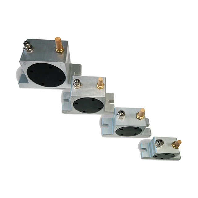
Four turbine vibrators lined up from the largest at the back to the smallest at the front. All four have the same shape: an aluminium body with a large round black cover, two connections on top with a brass silencer on one of them, and a wide foot with an open slot at each end. Only the dimensions change.

Four sizes, twelve models 50 · 65 · 80 · 100 mm

The range is four body sizes with three models in each. The three share all six dimensions, the thread and the whole air consumption, so what separates them is the speed and the force. The ATEX marking is the same on all twelve.

Body width, A50, 65, 80 and 100 mm
Models per sizeThree
Weight0.25 to 2.53 kg
ATEXII2G and II2D, category 2
  1. The size decides the room it takes. The model within the size decides the speed and the force.
  2. All twelve come with ATEX as standard.

There are no options for the OT: no timer, no solenoid, no ATEX kit and no mounting plate. There is one version of each model, and ATEX comes as standard.

Application

Where the OT belongs

Dry and granular materials, food includedThe range is meant for dry and granular powders: sugar, bicarbonate, phosphate and sodium. The OT is the only one of the three rotary ranges documented for food and pharmaceutical use.
Where oil mist is not allowedThe air does not have to be lubricated. The circuit is a filter, a flow control valve and a valve, the air quality is class 5.4.1, and no oil leaves the exhaust. That is what separates the OT from the S ball vibrator and the OR roller vibrator, which both want lubricated air.
Silo, hopper, chute and vibrating tableThe units bolt on the outside, and the vibration runs through the steel and on into the material. No hole is drilled in the wall, so the range can also go onto a plant that is already running.
Concrete consolidationConcrete in a mould has to settle tight. It is the large centrifugal force and the high rotational speed that make the range usable there, and the OT is the only one of the three rotary ranges where consolidation stands as a job in its own right.
Not on hot steelThe temperature limit is 120 degrees, and that is lower than on the other two rotary ranges. Where the steel is hotter, the OR roller vibrator reaches 200 degrees, and so do the adjustable F and the P piston vibrators.
Not for continuous runningThe duty is discontinuous. Where running has to be continuous, the pneumatic piston vibrators K and F are built for it, and the K also comes in a version that runs without lubrication.

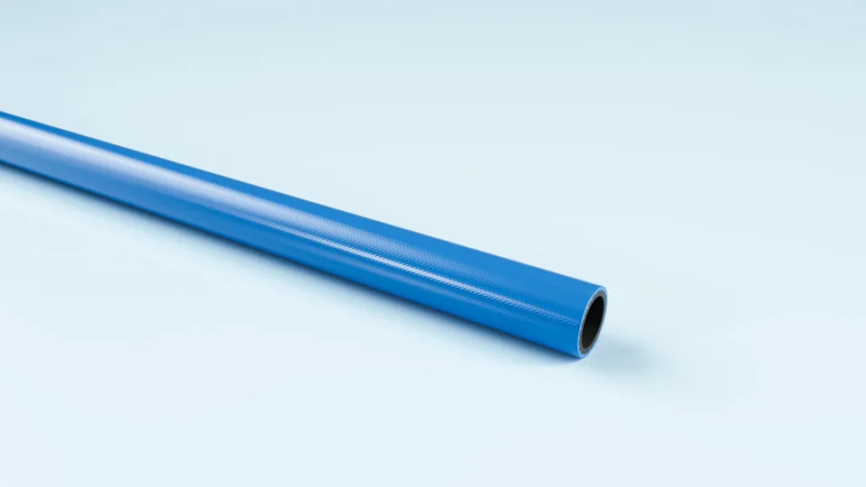
Blue polyurethane hose, coiled.

FlexCore

ARIAFORM/TPU

Light polyurethane hose for tools and reel systems. The softest of the three, and the one that suits the smallest 1/8″ connection.

Material
TPU
Inner diameter
6–13 mm
Working pressure
20 bar
Temperature
-30 to +80 °C

See the full product page on FlexCore →

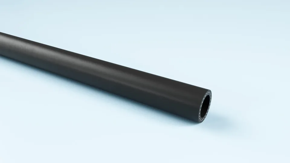
Black TPE air hose, coiled.

FlexCore

ARIAFORM/15

TPE air hose for industry and workshop. It handles both clean and oil-laden compressed air, so it can be used in a plant where the OT sits alongside a range that needs lubricated air.

Material
TPE
Inner diameter
16–25 mm
Working pressure
15 bar
Temperature
-30 to +80 °C

See the full product page on FlexCore →

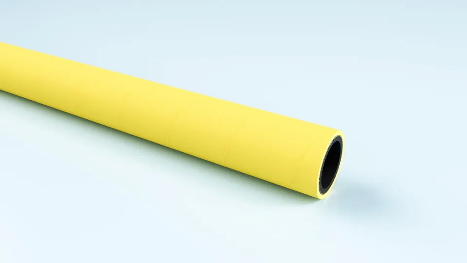
Yellow EPDM compressed air hose, coiled.

FlexCore

ARIACORD/YELLOW

Rugged EPDM hose for compressed air and water, 25 bar. Weather and UV resistant, so it can live outdoors.

Material
EPDM
Inner diameter
32–76 mm
Working pressure
25 bar
Temperature
-30 to +80 °C

See the full product page on FlexCore →

Portrait of a technical adviser at Particulair.

Technical advice

Which model, and how many?

Tell us what the silo, hopper or chute is made of, how thick the steel is, what you handle, how hot it gets, and how long it has to run at a time. We come back with a model, a number and a price, not with a catalogue.

Contact us Try the product selector